
When you’re looking for cost-effective bench-top tools for EMC pre-compliance testing, there isn’t much that can come close to the usefulness of a TEM cell.
Perhaps only seconded by a current probe, the TEM cell (or GTEM) offers a low cost method of measuring emissions from a product as well as being useful for subjecting your product to radiated fields.
In some circumstances, GTEM results are even accepted by the FCC for equipment authorization. Read on below to discover how.
In this article we’re going to cover:
- What is a TEM Cell?
- What are TEM Cells Useful For?
- Using TEM Cells for Radiated Emissions Testing
- Using TEM Cells for Radiated Immunity Testing
- Using TEM Cells for EMI Troubleshooting
- Different Types of TEM Cell
- GTEM uses
- GTEM to OATs Correlation
- FCC’s Rules for GTEM Cells
What is a TEM Cell?
‘TEM” stands for ‘Transverse-ElectroMagnetic (Mode)”. What does that mean?! Well, a transverse mode of electromagnetic radiation is a specific field pattern of the radiation in the plane perpendicular (i.e., transverse) to the radiation’s propagation direction. And a TEM cell is a rectangular-coaxial transmission line tapered at each end to form a geometry that is specifically designed to create the TEM mode over a given range of frequencies (typically DC to a few hundred MHz).
The useful frequency range of a TEM cell is dictated by its geometry, but generally follows the rule that the larger the TEM, the lower the usable upper frequency range. Above a certain cutoff frequency, higher order modes are created (shown below), which makes any measurements less stable across the test volume.
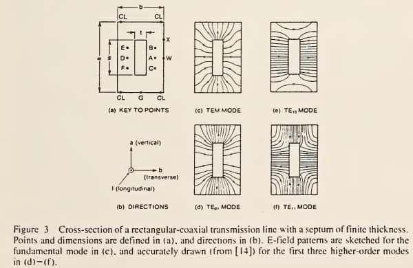
[Bandwidth Limitations of TEM Cells due to Resonances] Douglas A. Hill
“Perhaps the easiest way to explain a TEM is by what it does: A TEM allows you to measure the radiated field strength of a product as well as subject the product to a given field strength.”
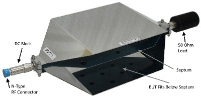
The main aspects of a TEM cell are shown in the image to the right (technically this is a ‘tri-plate line’ or ‘tri-plate open TEM cell’ because it includes one extra grounded plate on top) and they include:
- RF connector: for connection to a coax cable which in turn connects to either a spectrum analyzer or signal generator/power amplifier, depending on whether it’s being used for emissions or immunity testing.
- Outer shield: connects to the shield of the attached coax cable. On this tri-plate model shown, there are two grounded plates. Technically a TEM cell needs only one of the grounded plates.
- DC block: for protecting the sensitive input to an analyzer just in case there is a DC voltage accidentally applied to the septum.
- Septum: the centre conductor.
- 50 Ohm load: This is the termination of the transmission line. As with any transmission line, if there is no proper termination (i.e. a large mismatched load), you will get signal reflections.
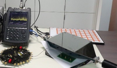
TEM Cell Construction
Here’s a closer look of how a TEM cell is made. For this I took apart my TekBox TBTC1 unit and snapped a few photos:
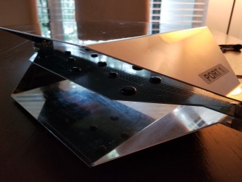
TekBox TBTC1
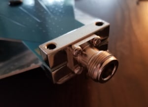
A standard 50Ω co-axial cable attaches to an N-type connector on one port of the TEM
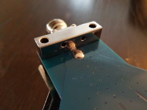
The shield of the coax splays out into the outer plates of the TEM cell
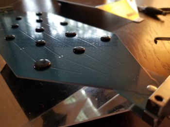
The centre conductor of the cable also splays out to a flooded copper area on the circuit board which forms the ‘septum’ of the TEM
The design is such that the electric field lines are fairly uniform between the septum and the outer plates.
A ‘test volume’ is created between the outer shield and the septum where the product under test sits. Within this test volume, the measurements are fairly uniform to within a few dB.
Data from TekBox shows that within a 12cm x 12cm x 9cm volume, measurements of a 500 MHz test signal vary by approximately -4dB to +5dB. In the world of EMC, that’s reasonably stable.
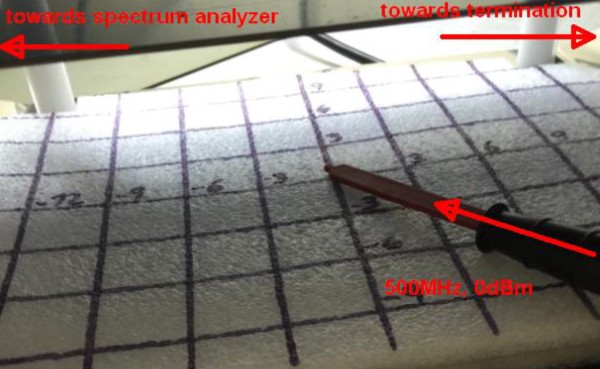
Characterization of the field uniformity within the test volume
What Are TEM Cells Useful For?
In the section below, I’ll dive into all of the various use cases for TEM cells.
Using TEM Cells for Radiated Emissions Pre-Compliance Testing
One of the primary functions of a TEM cell is to test the radiated fields emanating from a DUT (device under test). Engineers are always searching for that illusive method to figure out whether their product is going to pass or fail at a test lab. Near field probes won’t do it, because it isn’t possible to extrapolate accurately from the near field to the far field without phase information.
A wave travelling through a TEM cell has a free-space impedance of approximately 377Ω (up to an upper frequency boundary), which happens to be the impedance of a far-field plane wave propagating in free-space. In an OATS (open area test site) or a semi-anechoic chamber, the measurement antenna is placed at 3m or 10m separation, which corresponds to being positioned in the far-field at corresponding frequencies of 100 MHz and 30 MHz respectively. Therefore measurements made using a TEM cell have a close relationship to measurements made at a full-compliance test lab.
As an aside, this free-space impedance of 377Ω describes the relationship between the amplitude of the electric (V/m) and magnetic fields (A/m) in a similar way that a resistor of 377Ω relates the Voltage (V) to the Current (I) according to Ohms law. For full-compliance radiated emissions testing, the measurement transducers are usually log-periodic, biconical or horn antennas which are all sensitive to electric fields. Due to this free space impedance, we could equally measure the magnetic fields of our EUTs, but in terms of practicalities such as size and shape of the antenna, it is much more convenient for us to use E-field antennas.
Radiated emissions test setup
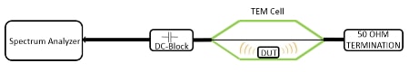
Radiated Emissions TEM Cell Test Setup
One of the benefits of the TEM cell is its simplicity. Connect one port to a spectrum analyzer via an optional DC block and the other port to a termination resistor and place your product between the septum and the outer conductor and you can begin measurements.
Tune your spectrum analyzer to the frequency range of interest and you’ll soon see if there are any suspicious emissions.
Ambient Noise
If you’re using an open TEM cell, then you will probably see ambient noise signals as well such as FM, Wi-Fi and cell phone radio transmissions. Open area test sites also have this issue. To determine if an emission is ‘an ambient’ or coming from the EUT, you can use a number of techniques:
- Turn off the EUT. If the emission disappears, it’s from the EUT.
- Move/rotate the EUT and see if the emission increases or decreases in amplitude.
- Decrease the span of your analyzer to focus only on one peak (e.h. span = 1 MHz) and reduce the resolution bandwidth (RBW) to 10 kHz or lower. This will often reveal an emission that was hiding behind an ambient at higher RBWs.
Noise Floor
A common issue with TEM cells is that an emission from an EUT may not be strong enough to be detected above the noise floor shown on a spectrum analyzer screen. There are a few options to improve the measurements sensitivity:
- Use a smaller (more sensitive) TEM if your EUT size allows.
- Insert a pre-amp between the TEM and the spectrum analyzer. Common pre-amp gains are 20dB or 40dB. A risk of going with higher gain is saturation or damage to a spectrum analyzer input stage.
- Reduce the internal padding attenuation in the spectrum analyzer to zero.
- Reduce the RBW setting of the spectrum analyzer.
- Use a shielded TEM (see section below for more information on this).
Between all of these methods, you should be able to see all narrow-band and wide-band emissions of interest.
Limitations of TEMs for radiated emissions measurements
It would be fantastic if TEM cells could tell us exactly whether our products will meet regulatory limits such as the FCC’s radiated emission limits.
There are a few issues that make this a bit of a challenge (but not impossible!):
- Often the radiating elements that cause RE failures, especially below a few hundred MHz, are the cables attached to an EUT. In small TEMs and even in larger ones, cable layout plays a huge part in the amplitude of the measurements. This is why I would recommend pairing a TEM cell with a current probe.
- Emissions tend to be directional (as opposed to isotropic), which means that the orientation of the EUT in a TEM can greatly effect the measurement. In some GTEMs, manufacturers try to overcome this issue by automating the measurement process. They perform measurements of the EUT in the X, Y and Z orientations and combine the measurements to produce one value which they claim provides a good correlation to a far field measurement. More details on GTEMs and correlations below.
Using TEM Cells for Radiated Immunity Testing
The other common use case for a TEM cell is radiated immunity testing.
A signal generator and power amplifier is connected to one port, and again the 50Ω termination resistor is placed at the second port.
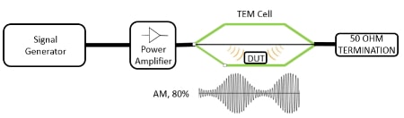
Radiated Immunity TEM Cell Test Setup
In this configuration, a very stable field is set up between the septum and outer shield.
The E-field, measured in Volts per metre (V/m) between septum and shield of the TEM is given by the simple equation:
E = V/d where V is the RMS voltage of the applied signal and d is the distance between septum and lower (or upper) conductive plane. This is based on the simplified assumption that the E-field is perfectly homogenous (i.e. evenly distributed).
A more practical formula is:
E = V*Cor/d where Cor is a correction factor for the average field strength over the volume of the EUT derived from the analysis of the field distribution over the cross section of the cell.
Specifically for the TekBox TBTC1, assuming the EUT is placed in the center of the cell and in the middle between the bottom plate and septum, the following formulas can be used with sufficient accuracy.
d = 5 cm E = (√(P*50Ω))*20
d = 10 cm E = (√(P*50Ω))*10
d = 15 cm E = (√(P*50Ω))*6.66
This yields the following field strengths:
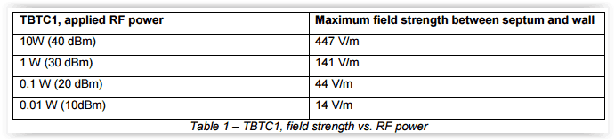
What you’ll notice here is that relatively high field strengths can be generated with relatively small amplifiers.
With only 0.1W , it is possible to generate 44 V/m in the TBTC1.
At a full compliance test lab, the equivalent test setup looks like this (according to IEC 61000-4-3):
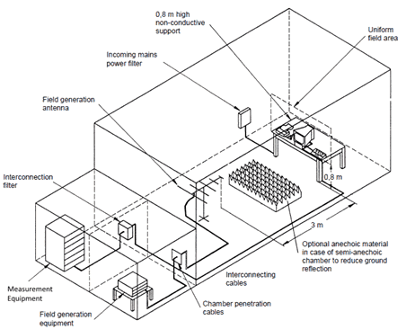
Radiated Immunity Test Setup
To generate 44 V/m in a test lab, you would need:
- Anechoic chamber ($500k – $1m)
- 2 or 3 high power antennas
- High power RF amplifiers (>$50k)
The TEM cell looks like a pretty good deal in comparison! This is why many manufacturers invest in a TEM cell or GTEM for radiated immunity pre-compliance testing and troubleshooting.
Some even use TEM cells for full compliance testing. More on that below.
Using TEM Cells for EMI Troubleshooting
TEM cells are especially useful for comparing configurations. If your product failed at an EMC test lab and you want to make modifications and test the effect of the modifications, a TEM will allow you to do that at your office rather than use an expensive test lab.
While a TEM won’t allow you to isolate exactly where on your circuit board an emission is generated, a low-cost set of near field probes will take care of that. The TEM comes into its own when you want to quantify the effect of changes to your PCB.
Due to the size, it is mainly useful for debugging PCB level issues.
Using TEM Cells for Component Evaluation
It’s no secret that seemingly identical components from different vendors can have radically different EMI performance. That’s one of the reasons I really recommend sourcing a few models and then evaluate their EMI performance in a TEM cell. You’ll quickly be able to see how they compare.
This technique is useful for evaluating components such as:
- LCDs
- IC modules
- Power supply modules
… to name just a few. I’ve seen components with equivalent specifications on paper vary in terms of EMI levels of +/- 40dB. This is a critical step.
Another ‘gotcha’ to watch out for is that some unscrupulous suppliers will remove ‘expensive’ filtering components after you have evaluated the golden unit that they initially provided to you. In these circumstances your first batch run of a product can have very different EMI performance to the pre-compliance testing that you did.
Using a TEM cell to benchmark production unit components vs the previously evaluated component will help to catch these issues.
Using TEM Cells for Monitoring On-Going Compliance After Component Changes
At the EMC symposium last year, I had the opportunity to ask EMC instructor Keith Armstrong what are the biggest trends in EMC that he’s noticed recently. His response was not what you might imagine.
One of the largest challenges he saw was that IC manufacturers were moving to shrink die in order to save on cost. In the process of shrinking the die, slew rates can decrease, peak RF current demand increases and therefore emissions can increase. Little or no mention may be made of these die changes, but this may push a product from compliance into non-compliance without a manufacturer knowing about it.
Testing a sample of units from a new production batch and comparing to benchmark results will again help to catch these sorts of issues.
Using (G)TEM Cells for RF Transmitter Measurements
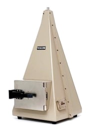
TESCOM TEM Cell
Another useful function of a TEM cell is to allow fundamental and harmonic emission testing of intentional transmitters.
In this great app note by a Nokia engineer working in the trenches, Stephen Clay describes his efforts at Nokia to correlate measurements made in a GTEM to those made in a chamber and on an OATS for their cell phones.
What he found was that with consideration made to getting the test setup right and by measuring in 4 orientations, he could achieve pretty good correlation.
Using TEM Cells for Isotropic Field Probe Calibration
Once of the main benefits of a TEM is the very stable and mathematically predictable field strength generated between the septum and outer plates.
This property can be used to accurately calibrate an isotropic field probe across a broad range of frequencies. One of the methods to do this is described in the paper “A method for calibration of isotropic E-field probes” by K. Matloubi.
Once calibrated, a field probe can somewhat ironically then be used to calibrate the field for radiated immunity testing in a semi-anechoic chamber.
Using TEM Cells for Shielding Effectiveness Testing
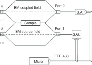
Using two TEM cells to measure shielding effectiveness of a material
Using a rare dual TEM cell, it’s possible to generate a known field in one TEM and measure the attenuated field accurately in another.
By placing a material under test in an aperture between the two TEMs, it is possible to precisely characterize the shielding effectiveness of the material.
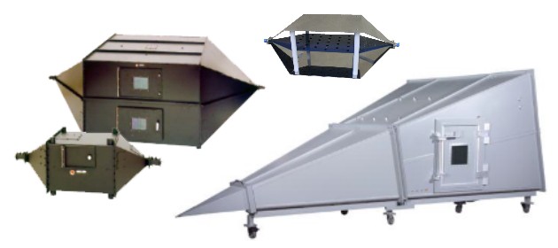
Different Types of TEM Cell
As you’ve probably noticed by now, there are quite a few different types of TEM cells. Read on below for some of the uses, pros and cons of each.
Open TEM Cell
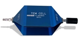
TekBox TEM Cell
An open TEM cell like the one shown in the image to the left are a good low-cost option.
Pros:
- Low-cost
- Lightweight and easily stored
- Large EUTs can be slid in from the side
- If the EUT is long, it can be tested at more than one point along its length
- No filters required for cabling entering/exiting the TEM
Cons:
- Open to receive ambient noise
- Radiated immunity testing may be illegal unless used in a shielded room or tent.
- Upper frequency limited to a few hundred MHz depending on TEM size
Closed (shielded) TEM Cell
Closed (Shielded) TEM Cell
Pros:
- Measurement of narrow-band ambient noise is reduced/eliminated
- Radiated immunity testing can be accomplished without fear of legal issues
- Overall noise floor is reduced
Cons:
- EUT size restricted to door size
- Getting cables out of the TEM is a challenge. Unfiltered cables will transfer noise inside/outside of the chamber so a custom filter panel is usually required
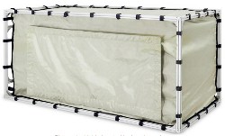
TekBox Shielded Tent
It’s also possible to use an open TEM within a shielded enclosure. This doesn’t need to be a shielded room – it can be a much smaller shielded tent structure like the one shown below.
The plot below is taken with (pink) and without (yellow) the use of a shielded tent. As you can see, the ambients are gone and the overall noise floor is reduced by 10-13 dB. This makes it much easier to discern what’s coming from the product you’re testing as well as potentially exposing emissions that would otherwise be buried in the noise floor of your test setup.
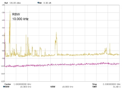
Unshielded (yellow) vs. shielded (pink) measurement plots
As an aside, a shielded tent like this has a similar effect on the noise floor for current probe measurements which may be required for automotive module tests. With the low limit lines specified in some standards, it can be a real challenge to achieve sufficient margin between the noise floor and the limits lines. A shielded room or tent can help with this.
GTEM
If you can’t afford a semi-anechoic chamber but you still want to perform emissions and immunity testing in-house, a GTEM is probably the next best thing.
I’ve written about GTEMs in the past such as in “The EMC Pre-Compliance Testing Guide” and “The EMC Testing Beginner’s Guide” emissions pre-compliance chapter. They are very useful tools, but they also have their limitations. Read on below for some pros and cons.
GTEM Cell
Pros:
- Can accommodate quite large EUTs
- Can be used for ‘full-compliance’ emissions and immunity testing in some circumstances (see section below)
- If a ‘boss manipulator’ is installed, it’s possible to obtain a good correlation to chamber/OATs measurements
- Measurements can extend up to 20 GHz or so depending on the model
Cons:
- EUT size restricted to door size
- Cable management can be a real issue
- Filter panel required to get all cables in and out of the GTEM
- Poor low-frequency response can reduce correlation to OATS measurements below a couple of hundred MHz
Amplifier Research ARCell
A variation on the GTEM is this ARCell from Amplifier Research. They’re no longer manufactured but you might see one out in the wild.
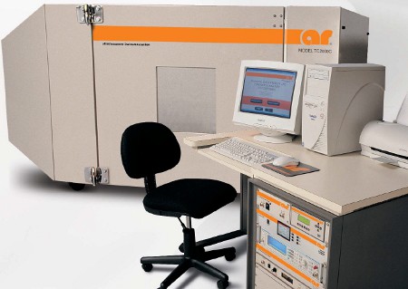
Amplifier Research ARCell
These are kind of a hybrid between a semi-anechoic chamber and a TEM cell. The interior of the ARcell enclosure is lined with RF absorbing material which creates a self-contained semi-anechoic enclosure. It includes two field launching and receiving devices. An internal log-periodic antenna acts as a launching/receiving device at higher frequencies and an optional bowtie antenna can be used at the lower frequencies. It allows both vertical and horizontal polarization.
Pros:
- Evolutionary design – Creates partial FAC inside cell
- Field uniformity achieved by using absorber to limit reflections
- Great for radiated immunity testing
Cons:
- Generally limited emissions accuracy
- Absorber reduces RF input efficiency, more power required to generate necessary field strength (typically up to 10 V/m at 80% modulation)
Others
There have been other variations of the TEM cell / GTEM over the years. These include the LaplaCell, Eurotem and WTEM. Each come with their own benefits and downsides.
TEM Cell to OATS/Chamber Correlation
One of the most common questions I get is whether it’s possible to use near-field probes or a TEM cell to figure out whether your product is going to pass or fail at an EMC test lab. Of the use cases I described above, this one is called ‘radiated emissions pre-compliance testing’.
Fortunately there is some good data on GTEM cell correlation to OATs and chamber measurements.
The most extensive paper I’ve found on the subject is “The Use of GTEM Cells for EMC Measurements” written by Angela Nothofer & Martin Alexander of the UK National Physical Laboratory as well as Didier Bozec, Andy Marvin and Les McCormack of York EMC Services Ltd.
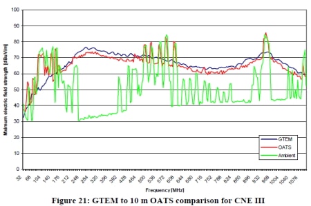
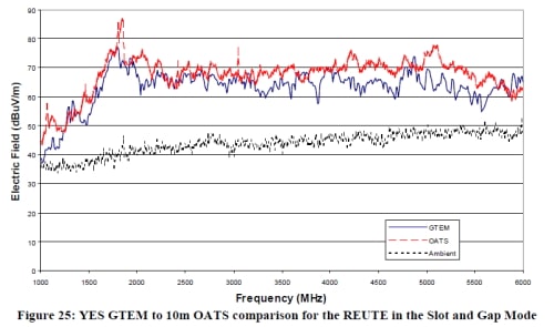
In the plots below taken from the paper, you can see that the correlation measured from 32 MHz up to 6 GHz in a GTEM using a CNE reference source are pretty decent. Note that to get these results, they had to take great care with the measurement method.
One of the main challenges when using a TEM cell for emissions pre-compliance testing is that very often, the dominant radiating source is not a circuit board, but the cables that connect to a circuit board. This is an issue at lower frequencies (below a few hundred MHz), and becomes less of an issue as the frequency increases. As the frequency increases, the dominant emission mode shifts away from common-mode towards differential-mode signals originating from circuit boards themselves.
FCC’s Rules for GTEM Cells
The correlation between GTEM results and results from an OATS/chamber are so good that in certain circumstances, the FCC will accept GTEM cell data.
In Public Notice GTEM PN 40830 released December 2, 1993, the FCC agreed to accept radiated emissions test data under limited conditions for Part 15 Equipment Authorization purposes. These conditions are:
” 1. Acceptable comparison measurement data must be filed with the Sampling and Measurements Branch accompanied by an appropriate analysis that demonstrates equivalence with an open area test site which has been listed as complying with the requirements of C63.4-1992. Comparison data must be provided for each general type of equipment under test (equipment of similar functionality and physical configuration, e.g. handheld transmitter, laptop computer, etc.) for which future acceptance of GTEM data is sought. Validity of calculated correlation coefficients must be supported by statistical analysis.
2. Acceptance of GTEM data for demonstration of compliance with radiated emission limits will be limited to the general type of equipment under test for which equivalence to open area testing has previously been demonstrated. Any cabling, either external or interconnecting, must be arrayed and terminated identically to the previously submitter equivalence demonstration.
3. In cases of disagreement, final radiated emissions test performed at an open area test site meeting the requirements of Sections 5.4.1 and 5.4.6 of ANSI C63.4-1992 take precedence. ”
Then, in Public Notice GTEM PN 54796 which was released July 12, 1995, they expanded the acceptance of GTEM results, again under limited conditions, to include rule parts other that Part 15.
In terms of guidance on the test procedure and data reporting you need to use, the FCC specifies “ANSI C63.4-2014 Annex F – Test procedure for emissions testing in TEM waveguides (30 MHz to 1 GHz)” and “Annex G – Sample OATS to TEM waveguide validation spreadsheet”. I recommend purchasing this standard if you want to explore this authorization route.
TEM Cells for Sale
We carry a number of new and pre-owned TEM cells for sale in the EMC FastPass store.
Conclusion
As you can see, a TEM cell is a versatile tool for any company to hold in their EMC equipment arsenal. For emissions pre-compliance testing, immunity pre-compliance testing, EMC/EMI troubleshooting, component evaluation and even FCC testing, the TEM cell is a great transducer capable of addressing many issues.
Comments 4
Great information. Thank you
Great to see more continued guides like this. This really is a comprehensive summary of what TEM cells are. We still use ours for pre-compliance so we have the best chance of what to expect, before we’d go to the lab.
Great illustration for pre-compliant test and troubleshooting by using TEM Cell. TEM Cell is like a must have tools for EMC/EMI engineers. Great job and thank you.
Pingback: GTEM (Gigahertz Transverse Electromagnetic) Cells: An Alternative to the Anechoic Chamber - EMC Insight