

Many manufacturers I’m sure would love to have an in-house anechoic chamber for radiated emissions, radiated immunity, or antenna (microwave) testing, but lack the space or budget. This article is for those manufacturers.
We’re going to cover some alternatives to fully compliant (semi) anechoic chambers that are much lower cost to build, such as absorber lined shielded rooms, foil/absorber lined office solutions, and even the notorious shipping container solution. And the most important thing is we’ll cover what to expect in terms of performance of these makeshift sites, so that we understand the trade-offs when compared to a fully compliant test facilities.
So here’s what we’re going to cover:
- Why Do We Need Anechoic Chambers?
- What is the Gold Standard for Radiated Test Sites?
- Efficiency and Cost Savings of Bringing Radiated Emissions Testing In-House
- Main Components of Anechoic Chambers
- Real Life Examples
- Pre-Compliance Chambers
- Microwave Absorber Lined Rooms
- Self-build structures
Why Do We Need Anechoic Chambers?
So why do we need anechoic chambers in the first place? Why can’t we just use an antenna to measure the radiated emissions coming from a product directly?
Ambient RF Noise
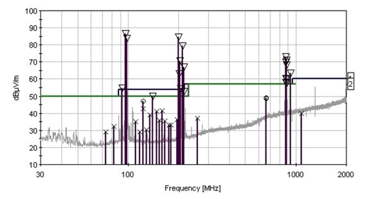
Noisy Environment on an Open Area Site
Well as I covered previously in The EMC Chamber Guide, a there are a couple of main reasons. The first is that there are just so many ambient noise signals floating around pretty much everywhere. The closer you are to a city the worse it gets. and in an office environment there are usually 10s or hundreds of sources of electromagnetic emissions that make it very difficult to measure emissions coming from one specific product.
So, what we do is we make a big, shielded box which acts as a Faraday cage to keep all the noise sources outside.
But measuring inside a shielded room is complicated by all of the reflections that bounce off the walls and ceiling and floor. The receiving antenna picks up multiple signal paths and shielded rooms also have resonances that depend on the size of the room, so what we need to do is to line the walls with RF absorbing material which converts the incoming wave energy into heat and therefore reduces the amount of reflections off the walls and ceiling.
By using this absorbing material we can make sure that we’re measuring predominantly the emissions coming from the product under test (plus the bounce off the floor in the case of a semi anechoic chamber). Any reflections off the walls or the ceiling are much attenuated by the absorber.
Prevent Illegal Broadcasting of RF Signals
Another reason to use an anechoic chamber is that very often we need to test product with a wireless transmitter that may not have been certified or licensed, so technically it would be illegal to transmit outside of a shielded environment. And the same is true of radiated immunity testing whereby the antenna transmits across a huge range of frequencies. This could cause all sorts of problems to other equipment and to safety critical wireless communication channels. The FCC can issue massive fines if you’re found to have been intentionally transmitting illegally (no pun intended).
So a shielded environment is useful in both of those cases.
Compact Space
Another benefit of using a semi anechoic chamber is that the measurement area can be quite compact, which is very useful when we have limited space in an office. Rather than have a very large cleared area as is the case for an Open Area Test Site (see below), the absorber reduces reflections and allows for a much smaller obstruction-free area requirement.
For larger manufacturers it isn’t uncommon to have multiple chambers situated side-by-side.
What is the Gold Standard for Radiated Test Sites?
If we’re going to create a pre-compliance chamber in-house, we better know what the best case scenario is. So let’s take a look now at some fully compliant test site configurations so that we can compare and contrast and look at the trade-offs when we’re trying to save money by building our own chamber.
Open Area Test Site (OATS)
So let’s start with an open area test site or an OATS. 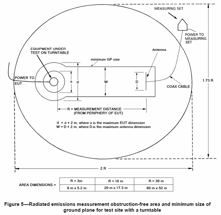 10 meter OATS are usually thought of as the gold standard of radiated emissions test sites. The reason being that we don’t have any reflections off the walls or the ceiling to absorb.
If an OATs has sufficient clearance around the measurement area, then the receiving antenna predominantly picks up the emissions from the product under test (plus the bounce off the metallic ground plane if applicable). If you want to build your own fully compliant OATS, the ANSI standard C63.7, “American National Standard Guide for Construction of Open-Area Test Sites for Performing Radiated Emission Measurements” is an indispensable reference guide.
Open area test sites were around a long time before semi-anechoic chambers existed, in a time where there were hardly any ambient transmission sources compared to today.
As more and more transmitters were deployed, more bandwidth was allocated and the number of IoT devices exploded, the need for semi-anechoic chambers has grown exponentially.
Many companies can and do install ad-hoc OATS inside or outside their buildings. Sometimes in loading bays, sometimes on a flat roof and sometimes in a field. The larger the clearance, the better.
Often the ambients are too restrictive though, hence the need for a chamber.
The focus of this article is not open area test sites, but there are several important characteristics that are useful to note before we move on.
Important Requirements
Some of the key features for a compliant OATS (for FCC measurements)
- +/-4 dB Deviation
The performance of an OATS is quantified using a “Normalized Site Attenuation” survey as described in ANSI C63.4, For measurements to be acceptable for the purpose of compliant measurements, an OATS must have a deviation of less than +/- 4 dB. If your in-house test site meets this criteria, then it performs as well as a fully compliant site.
- 1-4m Antenna Height Scanning
Fully compliant (FCC) test sites require the ability to scan the receiving antenna between 1 and 4 meters.
- 360° Turntable Rotation
Emissions from an EUT can be very directional, so it’s important to rotate an EUT to expose the receiving antenna to the highest emission level. Emissions can easily rise and fall by 20 dB or more as the turntable rotates, so without including one in a pre-compliance setup, your measurements could be very inaccurate.
- 3m/10m Antenna Separation
Some standards specify acceptable antenna separations (the distance between the EUT and the receiving antenna). For most equipment, a 3m antenna separation is acceptable, although some automotive and MIL standards call for a 1m separation. Ideally the measurement is being taken in the ‘far-field’, whereby the field strength decays predictably and small variations of antenna position do not make a large difference to the received signal.
If you don’t measure at the measurement separation specified in the relevant standard, this can introduce a large error. Measurement distances are explored in detail in Daniel Hoolihan’s excellent article here.
My recommendation would be to measure at a minimum of 3m separation, unless the relevant standard specifies a shorter separation (such as 1m for CISPR 25).
- Horizontal/Vertical Antenna Polarity Selection
Often the antenna orientation can mean a measurement difference of 5-10dB. This is due to the fact that when the antenna shares the same polarization as the emissions source, the pickup will be much greater than if it was orthogonal. For this reason, it is very important to be able to switch the antenna polarization between horizontal and vertical. Without the ability to switch antenna polarizations, your measurement could be off by 10 dB or more.
Therefore for your pre-compliance test site, it’s important to be able to change the orientation of your antenna between horizontal and vertical.
Compliant Semi-Anechoic Chamber for FCC (or similar) Measurements
The goal of a compliant semi-anechoic chamber is for the measurements to be equivalent to those taken on an OATS. So for this reason, all of the requirements I’ve just talked about apply.
The main additional requirement is for the characteristics and performance of the absorber material. Some standards specify a minimum acceptable reflectivity of absorber (e.g. CISPR 25 specifies -6dB), whereas other standards only specify chamber qualification metrics for the full chamber. In those cases, the type and position of the absorber material is critical in meeting the qualification criteria.
Key Qualification / Validation Tests For Compliant Chambers
NSA Deviation
The NSA method or normalized site attenuation method is the most commonly used method to qualify the measurement performance of an OATs or semi-anechoic chamber in the frequency range 30 MHz – 1 GHz.
As I mentioned before, the maximum deviation permitted for a compliant test site in accordance with ANSI C63.4 is +/- 4dB.
If a test site does not meet this deviation, then the measurements are not permissible for compliant measurements for FCC authorization. For pre-compliant test facilities it doesn’t matter if the site meets this requirement, but the larger the deviation, the larger the possible correlation error between the pre-compliant site and a fully compliant site.
The test method for this qualification test is detailed in the appendix of ANSI C63.4,
In a semi-anechoic chamber, ferrite tile is required to achieve a reasonable NSA performance. Microwave absorber alone typically does not perform anywhere near as well as ferrite below a couple of hundred MHz. So if you intend to make radiated emission measurements in a pre-compliance chamber below 200 MHz, then ferrite is really needed. Without it, there will be significant reflections and the measurements will be wildly inaccurate at certain frequencies due to resonances and multipath.
sVSWR
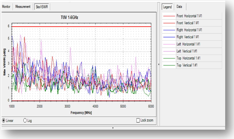
Example sVSWR Plot
For measurements above 1 GHz, we no longer use the NSA survey to qualify test sites. Instead, the site voltage standing wave ratio test is used. The sVSWR method as described in CISPR 16-1-4 is the preferred method for qualifying chambers and open area test sites in the frequency range 1 GHz up to 18 GHz.
The sVSWR test determines the size of the test volume that can meet the 6 dB limit. If the chamber is too small or the performance of the absorber on the walls or the patch on the floor between the EUT and the antenna is not sufficient, then it can be tough to achieve this requirement.
The most common way to improve the performance of this test is to increase the reflectivity of the absorber patch on the floor. Either increase the size of the patch, or change the absorber to a higher performance type.
Shielding Effectiveness
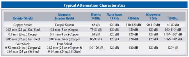
Most completed chamber installations are tested for their shielding performance.
The shielding can attenuate ambient signals by as much as 120 dB over a frequency range covering kHz up to tens of GHz. The magnitude of the attenuation depends on the quality of the materials and construction of the chamber, and typical areas that reduce shielding effectiveness are at any penetration points such as the doors, the cable filter panels and the air vents. These are typically the weak points of shielding effectiveness in a chamber.
In addition to the metal shielding, a full treatment of microwave absorber will increase the measured attenuation, often by 10-20 dB.
If you plan to line a room with foil (a good way to approximate a shielded room – examples of this towards the end of the article), ANY penetrations of the foil will degrade the shielding effectiveness of the room. Anything such as light fixtures, electrical outlets, windows, ceiling vents, doors etc will degrade the shielding effectiveness. If you want the highest shielding effectiveness, it’s important to use a feedthrough filter to filter every single penetration.
From ETS Lindgren ‘Double Electrically Isolated RF Enclosures’
In terms of target shielding effectiveness, 90dB of attenuation is typically more than enough to attenuate all signals below the noise floor of almost all test setups. The only exception to this is if you have a high power transmitter in the vicinity and you need to measure extremely small signals and have an exceptionally low noise floor with a high spec receiver and awesome pre-amplifier, in which case you may need to go for the highest spec of chamber that can achieve higher attenuation.
Others
There are many more chamber qualification tests that can apply, such as the long-wire method, but they’re beyond the scope of this article.
But the point is that when you’re building your in-house test site, these qualification tests are the ultimate gauge of its performance.
But once you have your in-house site up and running, your company can enjoy many benefits.
Efficiency and Cost Savings of Bringing Radiated Emissions Testing In-House
Most manufacturers are aware of the potential time and costs associated with EMC testing (and potential failures) so I won’t spend much time on this.
But as a quick summary, by building an in-house chamber, it can have the following benefits:
- Avoid commercial test-house costs, often costing >$250 USD/h
- Avoid chamber lead time issues (get into the chamber whenever you need)
- Avoid minimum booking time (often 4 hours). Just nip in to do a quick test
- Use for troubleshooting and don’t pay for time while performing modifications/fixes
- Qualify components (test samples from different vendors)
- Get to market faster
These are just some of the reasons that companies look to build in-house chambers.
So let’s take a closer look at what constitutes a good chamber.
Main Components of Anechoic Chambers
Chambers aren’t rocket science. At the most basic level, a chamber is a tightly RF sealed metal box with absorbing material on the walls and ceiling to reduce reflections. The implementation of that concept differs slightly between applications or manufacturers, but they all share that same goal.
I’ll highlight some of the most important components below that are relevant when considering your own in-house solution.
Structural + framing
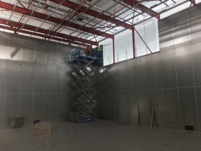
10m EMC Chamber Under Construction
Depending on the size of chamber you’re looking to build, it’s very often necessary to have a supporting steel structure. Given the weights involved such as steel panels (~4 lb per sq ft), and ferrite panels (~10 lb per sq ft), a very substantial support structure is usually required.
The shielding panel weight can be mitigated significantly when using the copper/aluminium foil solution (see examples toward the end of the article), but there is really no way around the ferrite weight as I will cover in more detail below.
Microwave absorber is much lighter and can typically be supported without additional framing.
Chamber Penetrations
As I mentioned earlier, in order to preserve the shielding effectiveness of a chamber, every single penetration of the shield must be filtered. This is because any wire can very easily conduct noise from outside a chamber to inside. Specialized feedthrough filters are used for power and communication circuits to prevent this from happening.
Some examples are shown below:
Power Filters
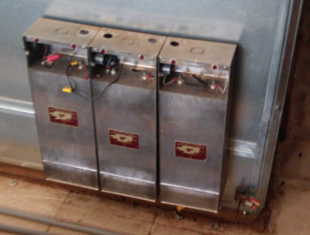
Feedthrough RF Power Filters
Feedthrough power filters are used for AC or DC power supplies. Any power wiring that is inside the shielded area should be passed through a filter like this.
Power filters typically come in 5A, 30A, 60A and 100A sizes as well as single or 3 phase configurations.
Sometimes individual feedthrough filters are provided for each light fixture, but more commonly a dedicated lighting circuit is routed through one power filter and then distributed throughout the chamber.
Communications/RF Filter Feedthrough Panel
Again, when passing any cable through the shield, it must be filtered to avoid degrading the overall shielding effectiveness of the room.
Sometimes you’ll see an open pipe feedthrough that is not filtered. As long as the pipe diameter is small enough and it’s long enough, the effect on shielding effectiveness can be minimized.
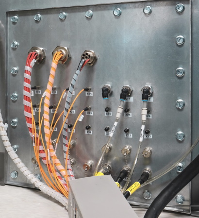
Comms Filter Panel
Vents
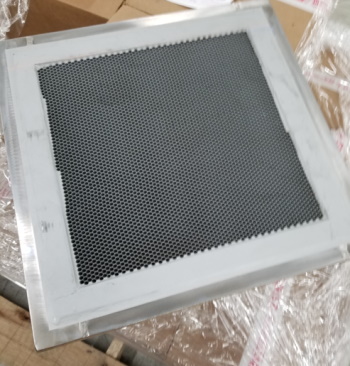
RF Shielded Vent
Any aperture in the shield is a potential weak spot for RF leakage. That includes things like windows, doors, cracks, vents, light fixtures etc. For that reason, even air vents are specially designed to minimize leakage.
RF vents include a metallic multi-layered honeycomb structure that allows air to pass through, but provides enough electrical conductivity to maintain a very high shielding effectiveness across a broad range of frequencies.
For self-build rooms, you must consider all penetrations including the HVAC system.
RF Shielded Doors
RF shielded doors are a critical component in the robustness of an RF shield. They are very typically a weak point in terms of shielding effectiveness. I think due to the fact that they have to be moved repeatedly, the RF gasketing mechanisms often fail over time.
Sometimes there is oxidization and sometimes ‘finger stock’ can break, leading to a degradation of the electrical contact between the door and the door frame.
This is why it’s important to inspect your RF door and service it whenever necessary. The finger stock can be replaced and often any oxidization can be removed. By doing this, the shielding effectiveness can be maintained.
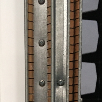
RF Door Gasket Fingerstock
In the image to the left you can see an example of ‘finger stock’ in a double sealed sliding door. With RF seal configurations like this, a shielding effectiveness of 125 dB or so could be achieved up to 40 GHz. Single knife-edge doors might achieve more in the range of 110 dB isolation.
For self-build chambers, it is worth considering how to deal with any access doors.
Shielded doors can often be retrofitted into a foil lined room. You can see examples of this towards the end of the article.
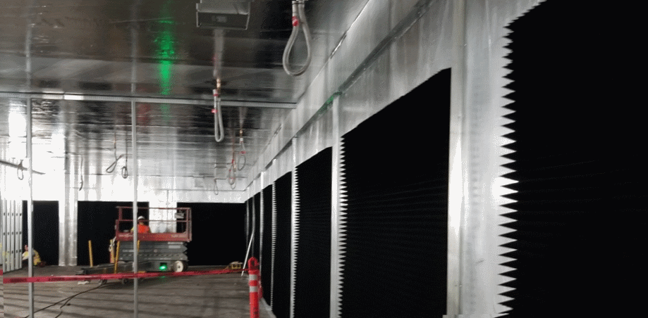
Ferrite Absorber
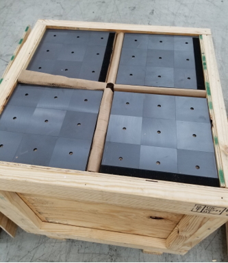
Ferrite Panels (Low Frequency Absorbers)
Without absorbers, there would be lots of reflections inside the chamber from the EUT emissions, and the antenna would pick up multiple signals from the same source. Therefore, the received signals would be completely uncalibrated and the chamber would be non-compliant.
By adding absorbers, we turn the incident electromagnetic wave energy into heat energy.
We use ferrite tiles to absorb the lower frequencies of 30 MHz to 1 GHz, and we usually place hybrid pyramidal absorber wedges on top of the ferrite which is designed to absorb higher frequencies above 1 GHz.
Now, a closer look at the absorber properties shows that the ferrite return loss varies quite significantly with frequency and also with the incident angle of the wave. If the wave is perpendicular to the tile, we get the maximum return loss, or absorption, which can be in the order of 20db-40dB which means it absorbs more than 99% of the incident wave energy and converts it into heat.
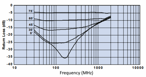
Ferrite Wide Angle Return Loss
As the incident wave becomes parallel with the ferrite though, its effectiveness reduces, and at 45 degrees you’re looking at only around 10 – 15dB loss.
Still, ferrite is required to meet the requirements of the NSA test for frequencies between 30 MHz and around 300 MHz where the pyramidal absorber begins to kick in. Without ferrite, we wouldn’t get enough absorption in this frequency range and we’d see lots of reflections off the shielding panels.
But since we’re usually testing above 1 GHz as well, and ferrite isn’t particularly effective above a GHz, you’ll also usually see microwave absorber installed on top of the ferrite.
RF Microwave Absorber
Microwave absorber is typically based on a substrate and loaded with carbon. The carbon is lossy and absorbs electromagnetic energy and the substrate material can be many different types such as polyurethane or polystyrene.
The material affects not only the absorbing performance, but also other characteristics such as power handling capability which sometimes comes into play if you’re dealing with high field strengths in your chamber for radiated susceptibility testing.
The length of the wedges has a major impact on their performance though, with the shorter wedges typically reserved for higher frequencies (see table below).
If the chamber is only going to be used for high frequency RF transmitter measurements, then there may be no point installing very expensive ferrite panels, and you could perhaps get away with only installing 4” pyramidal absorbers instead.
LightingAnother important aspect of chamber design is the lighting. LED or fluorescent lights are a very common source of electromagnetic interference. So we definitely don’t want to use standard off the shelf lights.
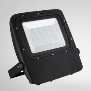
Low EMI LED Floodlight
You can read about ‘Minimizing EMI from LED Lighting‘ in a previous article, and you can see the effect of standard LED lights on ambient noise in a video here.
EMC FastPass does offer low-EMI lights that were specifically designed and tested for shielded room/ anechoic chamber applications.
In the plot below of the low-EMI LED floodlight radiated emissions profile, the noise of the floodlight is below the noise floor.
LED Floodlight EMI Performance
Labour Costs
The final thing I’ll mention here is that labour costs when installing a chamber can be a very significant portion of the overall project cost.
Experienced installers with a solid knowledge of RF are quite hard to come by, so their hourly rate tends to be high. It isn’t uncommon for labour to account for 20%-30% of a compliant chamber installation project.
But without experienced installers, it’s likely that the performance will be somewhat lower due to not knowing many tricks of the trade required to build a high performing room.
To save on cost, a manufacturer will sometimes hire an experienced site foreman to oversee the installation and will provide strong labourers themselves.
5 Low(er) Cost Chamber Options
Now that we’ve covered the main chamber components and what the gold standard is for fully compliant test sites, let’s take a look at some much lower cost options.
Pre-Compliance EMC Chambers
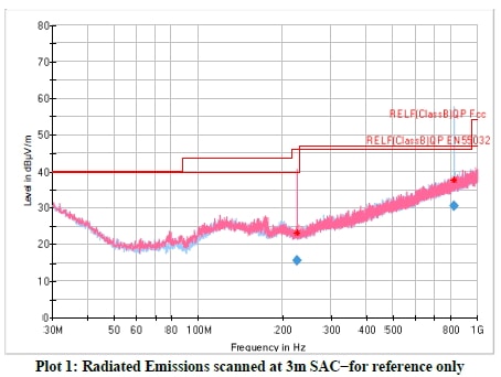
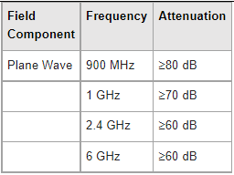
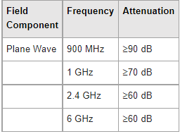
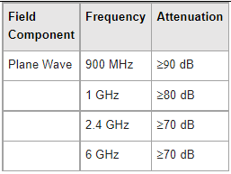
For every 1 fully compliant chamber, chamber manufacturers typically sell several pre-compliance chambers. The main reasons being that they’re typically less than half the price and they take up much less space. And all that with only a very small reduction in performance.
As you can see from the performance table below for the compact EMC chambers that we offer the performance is extremely close to that of a fully compliant chamber.
The only non-compliant performance metric is actually the NSA deviation in the frequency range 30 MHz to 100 MHz, and even that is only out by 0.5 dB (+/- 4.5 dB vs the requirement of +/- 4 dB).
For the rest of the frequency range, all the way up to 18 GHz, the chamber meets NSA and sVSWR requirements.
Given the height of the chamber, the antenna height is restricted to ~2.5m, instead of the FCC’s requirement of 4m. However it is relatively uncommon to find an emission maximum above a couple meters, so this doesn’t have a large impact of measurement correlation.
If you have space and budget available, these are an excellent option.
It can be used for fully compliant radiated immunity testing as well as pre-compliant emissions testing.
Foil & Microwave Absorber Lined Rooms
But if your goal is to create a room on a more modest budget, below I’ll give some real-world example projects that highlight different methods to save money.
The usefulness of each of these really depends on the application. Sometimes only shielding is required; sometimes only high frequency absorber is required (e.g. for transmitter/antenna testing), and sometimes ferrite is required (for lower frequency radiated testing).
But the overarching theme for the projects below is that a pre-manufactured chamber is not always needed.
Example Project #1
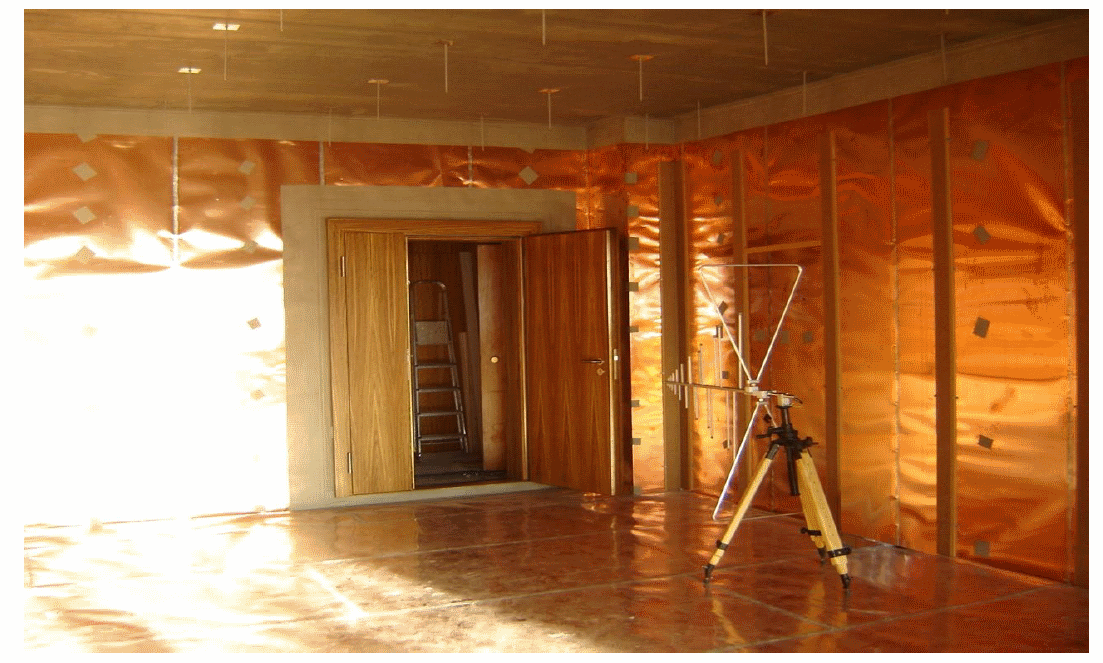
One way to cut out a large percentage of chamber cost is to line the walls of an existing space with copper or aluminium foil.
In a representative project, a large room was lined with aluminium foil on the walls, ceiling and floor. To provide decent attenuation, the rolls of foil were overlapped by 6″ and then taped with standard aluminium foil tape.
Project #1 Shielding Effectiveness
Notice that there was no need for heavy structural framing or for dedicated shielding panels.
Some important points about this installation:
- All MEP (mechanical, electrical and plumbing) were RF filtered the penetrations
- Access door was fitted with RF shielding gasket treatments
With this configuration, the room achieved the shielding attenuation figures shown in the table to the right.
Example Project #2
In a very similar project to the one above, there was an addition of specular VHP-4 broadband absorber treatment.
Project #2 Shielding Effectiveness
Again, a similar configuration as before, only with specular 4″ absorber treatment.
- All MEP (mechanical, electrical and plumbing) is RF filtered
- Access door has RF shielding gasket treatments
- Walls treated with VHP-4 (4″) broadband absorber
In general, the addition of microwave absorber on top of a shield will provide some additional attenuation across a broad range of frequencies (dependent on the type and size of absorber used). For example, standard 18″ absorber wedges may provide an additional 10-20dB attenuation on top of the shielding layer, if 100% coverage is applied (not specular).
For this project, a slightly higher attenuation was measured around 900 MHz.
If the room was instead fully lined with ~18″ absorber, I would estimate the attenuation all the way up to >6 GHz would bump up at least another 10 dB.
Example Project #3
In this project. copper foil was used. This picture was taken during construction and the installation is not complete.
Project #3 Shielding Effectiveness
The configuration of this room was as follows:
- All MEP (mechanical, electrical and plumbing) were RF filtered
- A high performance RF shielded door was installed and properly connected to the copper shield
With this configuration, you can see that the room achieved an additional 10dB attenuation across the board. This shows the importance of a well sealed RF door.
Other Examples
Open Microwave (Antenna Measurement) Site
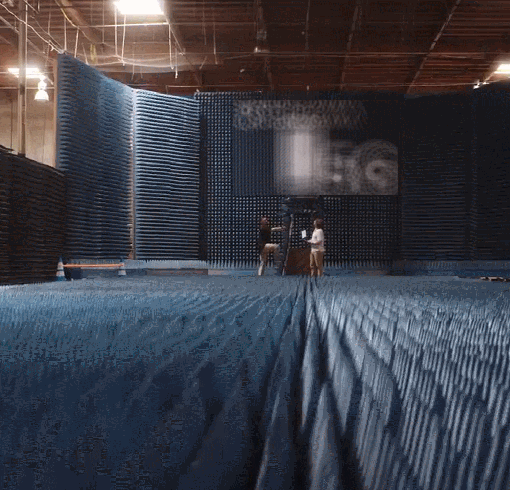
Makeshift Antenna Measurement Test Site
This RF test area popped up in an ad on Linkedin recently. It looks like it’s for a specific antenna measurement application.
Interestingly this does not include a shield and instead uses only tall wall structures lined with what looks like 12″ or 18″ microwave absorber.
In this case, there are a few notable things:
- The site is very large, so reflections off conductive objects will be greatly attenuated by the time they reach the measurement antenna
- Microwave absorber alone can act as a shield
- The large floor absorber area is used to absorb the radio wave ‘bounce’ off the floor. The goal is for the receiving antenna to receive only the signal directly from the AUT (antenna under test), as in the case of a free-space environment
- When measuring antennas with high gain (i.e. quite directional) and high frequency, expect less ‘bounce’ off the sidewalls and ceiling. This can be used to your advantage to save on the need for absorber material
- Since this test site is not in a shielded enclosure, if an antenna is transmitting, legally it must either have already been certified by a regulatory body such as the FCC, or the manufacturer must obtain an experimental license/authorization
Shipping Containers
Shipping containers are an attractive solution to some manufacturers. They’re a big shielded box aren’t they? Well not really. The joints are not designed with RF in mind, so you’ll find very significant RF leakage unless you seal it up properly yourself with liberal amounts of copper or aluminium tape.
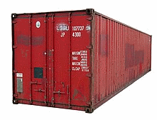
Shipping Container for RF Measurements
The second major issue is size. Shipping containers come in standard widths and heights, which are restrictive, especially once 12″ absorber has been fitted internally. This can have the downside of near-field effects between the EUT and the absorber which increases the NSA deviation performance, especially at lower frequencies where the wavelength is longer.
However they can undoubtedly be useful as they can easily be dropped in a parking lot and very quickly fitted with microwave absorbing material.
With microwave absorber only (without ferrite), I would take an educated guess that NSA performance would be +/- 6 dB from ~200 MHz upwards.
Below 200 MHz, unless ferrite is fitted, I wouldn’t expect any better than +/- 20 dB, due to reflections. For antenna testing, this may not be a problem at all.
Pros
- Very low cost
- Can be fairly easily retrofitted to provide OK shielding performance
- Easy to drop in a parking lot or field
- Could potentially fit ferrite allowing for <200 MHz measurements
Cons
- Very limited internal width (7’8″) that will limit the test volume
- Limited height (7’10”) limits antenna scan height
- Corrugated metal walls will produce unpredictable reflections
- Door and all joints are typically RF leakage points and will likely need to be sealed
In the image tp the right, a shipping container has been retrofitted with a high performing RF door, power/comms filters and an RF sealed vent.
This solves the door leakage problem and provides a way to get power and comms into the container whilst maintaining shielding effectiveness.
Contact us ([email protected]) if you’d like a quote on an RF shielded door.
Wooden Structures
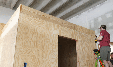
Wood Construction Room for RF Testing
And finally I want to mention one last option.
And that is rather than retrofitting an existing room or using a shipping container, you could also just construct a wooden structure yourself and line it with foil.
With a bit of elbow grease, this method could easily save tens of thousands of dollars when compared to a full shielded enclosure option.
And all of the things we’ve already covered such as filtering cable penetrations and properly RF sealing any apertures will provide the highest level of shielding.
Radiated Emission Measurements Below 200 MHz without Ferrite
RF Current Probe
You may have noticed by now that most of these makeshift test sites do not include ferrite tile lining.
If you need to make radiated measurements below around 200 MHz inside a shielded enclosure, without ferrite the reflections and resonances will be significant, leading to wildly inaccurate measurements.
There are really only 3 solutions to this:
- Install ferrite tile (not often possible given the weight (~10 lb / sq ft) and cost)
- Use an open area test site instead, with ample clearance to the nearest reflective surfaces/objects
- Use RF current probes instead
RF current probe measurements extrapolate to far-field radiated electric field strength measurements fairly well in the lower frequency range (e.g. 30 MHz – 200 MHz) where common-mode current on external cabling tends to be the dominant radiating element. I cover this in detail in the ‘Current Probe Pre-Compliance Testing Guide‘, so check that out if you’re looking for a low frequency solution whilst using a microwave absorber lined shielded room for higher frequency measurements.
Summary
Ok, that’s it for this article.
In summary, if you want to create an economical in-house test site:
- Copper/Aluminium foil lining can provide good shielding and act as a replacement for heavy shielding panels
- All shield penetrations should be filtered
- Rooms can be lined with RF absorber to provide excellent performance above ~200 MHz
- For radiated measurements below 200 MHz without ferrite absorber, 2 alternatives are (i) increase the clearance around the test area or (ii) Use a current probe to measure cable radiation
I hope this provides some inspiration for your next in-house test site!
Comments 3
Great article! Answered lots of our questions on what direction to take for inhouse pre-compliance testing
Hello Andy, useful article! Just an add about the GTEM: read our solution to reduce the conducted interference in low frequencies at: https://gtemcell.com/wp-content/uploads/2013/01/Ferrite-table.pdf
The table is 2″ suspended to allow the passages of cables down and their radiation plus reflected components from the floor of the cell are attenuated by ferrite! This trick helps a lot to improve GTEM applications!
Fiorenzo De Lucia
Project manager
GTEMCELL.COM
Great work. This was a good refresher on these topics. Very useful, thank you. I continue to look for your articles.