
EMI (electromagnetic interference, or ‘noise’ for short) from LED lighting is a very common issue. It may cause interference issues such as disturbing radio signals in the vicinity or it could just be an issue for passing regulatory hurdles such as FCC or CE. In this case study, I’ll focus on a 100W LED floodlight that I recently tested and had manufactured in Asia. For the specific application, this floodlight had to have an extremely low noise level, so I’ll show what it takes to achieve that.
Here’s what we’ll cover:
- How is EMI generated in LED lighting?
- Preparing for EMC testing
- Baseline performance
- Adding a filter
- Adding ferrites
- Comparing off-the-shelf LED drivers
- Effect of active harmonic suppression
- Summary of methods to minimize EMI from LED lighting
Let’s get started!
How Is the EMI Generated in LED Lighting?
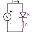
Simple LED Circuit
LEDs are simple semiconductor devices that emit light when a large enough forward voltage is applied across its terminals and current flows.
To generate light, the voltage across the terminals must be larger than the forward voltage drop of the LED. After the voltage has increase past that point, the brightness
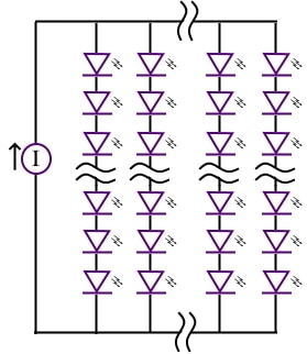
LED Light Strings (Protection Not Shown)
increases proportionally with the current passing through it.
When driving high power LED lights, there are often several LEDs connected in series, and several parallel strings of LEDs as shown to the left.
The driver in this case study is used in constant current mode, although it is also possible to use constant voltage supplies.
The LEDs themselves are either driven at DC (not switching) or by PWM (pulse width modulation). PWM is often used to reduce overall power consumption, taking advantage of a trait of the human eye, whereby short, high frequency bursts of light can be perceived to be almost exactly the same brightness as a light that is constantly on.
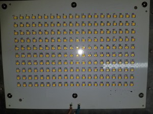
Array of LEDs on a PCB
If the frequency is high enough, a reduction to 50% duty cycle (off for 50% of the time) may result in negligible perceptible loss of brightness.
However, when using PWM, significant harmonics can be generated up into the hundreds of MHz which can easily cause high emissions from LED cabling.
For the light in this case study, we’re dealing with DC current driven by an off-the-shelf constant current source.
The current source is essentially an AC-DC power supply, and this is the source of the EMI.
As I’ve covered in this video on current loops, this video on DC-DC power converters, and several hours in the ‘EMC Design for Compliance: Emissions‘ online course, the source of many a radiated and conducted emissions headache is the switching within a switch mode power supply. It is no different in this case.
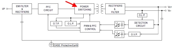
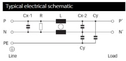
LED Driver Block Diagram [Meanwell] And The Noisy Culprit
As we’ll see in this case study, all LED drivers (or power supplies) are not created equally! And even though I was using an off-the-shelf driver, there are still some levers available to reduce the radiated and conducted emissions performance.
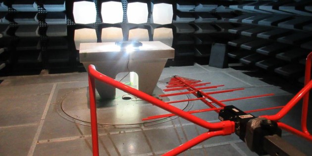
Preparation for EMI Testing
It’s no secret that time in an EMC test lab is expensive, and it goes incredibly quickly, so it’s best go as prepared as possible.
My strategy for success at the EMC test lab included:
- Perform pre-compliance testing before going to the lab including current probe measurements and flicker/harmonics testing
- The current probe measurements were below the noise floor, so I didn’t pick up any major emissions issues. The flicker/harmonics testing will be discussed in a later section.
- Bring 3 different LED drivers for comparison
- I had a preferred driver due to cost and availability, but I brought backups from 2 different manufacturers just to try out.
- Bring filter modules for the input and output of the LED driver
- These off-the-shelf filter modules are designed for DC (output) and AC (input) applications
- Bring additional shielding options
- I didn’t need to investigate this route
- Bring a selection of clip-on ferrites
- For this application, the additional cost of ferrites was not prohibitive, so I brought a Wurth ferrite kit for this.
- Have all contingencies pre-installed (but unconnected) or as close as possible to installation-ready
- So much time can be eaten up at a lab when soldering and opening/closing units. Pre-install contingencies to save time.
The baseline LED light configuration is shown below:
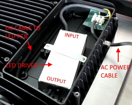
Baseline Performance
So, the first scan of the LED light yielded the following results:
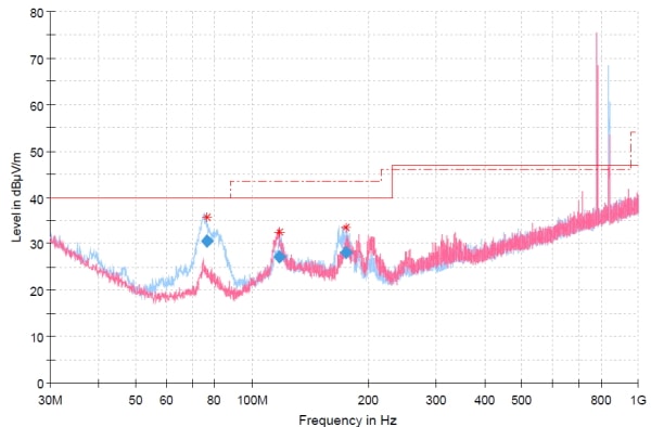
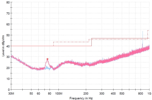
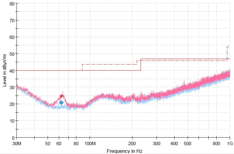
Baseline Radiated Emissions Performance
Ignore the emissions around 800 MHz – these are ambient signals in the cell phone bands.
The other bumps are from the light, with blue (vertical antenna polarization) and red (horizontal antenna polarization). The vertical polarization is much worse, which is not uncommon. This is mostly due to the only cable exiting the product (the AC power cable) running vertically from the test table to the floor. The emissions from this cable couple more efficiently when the receiving antenna is polarized in the same orientation.
Normally this would be considered to be an awesome result. The worst case emission is approximately 10dB below the limit line. But for this particular application, it was very important to reduce any emissions below the noise floor, or close to it.
Celebratory rum and cokes would have to wait, I had some work to do!
Modifications to base unit
I then incrementally implemented some of the prepared tests, which are shown in the photo below. These tests were not to prove a production ready solution, they were just to find out where the levers were in the design, so a more elegant solution could be found.
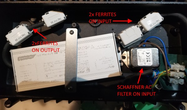
Adding a Schaffner Filter
Schaffner FN2020 General Purpose Filter
The first thing I implemented was to connect up the pre-installed filter shown above. The filter was a general purpose AC/DC filter from Schaffner, with block diagram as shown. This offers both common-mode and differential mode attenuation, and I expected it would help quite a bit.
The result of that one change is shown below:
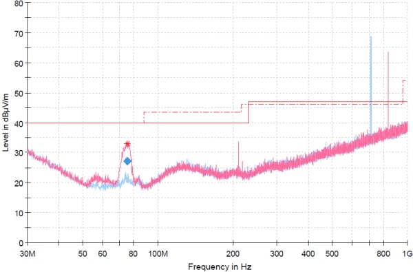
Radiated Emissions With AC Filter Inserted
This significantly attenuated the majority of the emissions apart from a stubborn peak at around 75 MHz. The other visible narrowband peaks are ambients.
Add Ferrite(s) on AC Cable
The next step was to add a clip-on cable ferrite external to the unit which resulted in the following improvement:
With Schaffner Filter & 1 External Ferrite
That brought down the peak by approximately 5dB. Typically a single pass through ferrite can attenuate noise by 1-10dB.
Then I added 1 more ferrite externally, which resulted in the following:
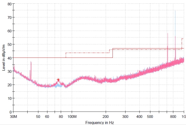
2 External Ferrites + Schaffner Filter
This was close to acceptable, with only one peak approximately 4dB above the noise floor.
Adding several more ferrites internally in the unit did not improve the emissions any further. In fact in some cases they made it worse.
Still, with a filter module and 2 ferrites, this wasn’t an ideal solution.
Time to try another LED driver.
Switching out the LED Driver
Quickly switching out the LED driver as the time ticked down to the end of the allocated time at the EMC lab, and also removing all of the filtering/ferrites that were previously applied yielded the following result:
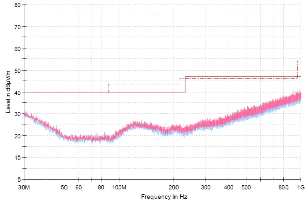
New LED Driver – No External Filtering or Ferrites
This was an amazing result. The new driver achieved performance better than the previous driver, even without an external filter.
The filtering internal to the driver was much better, both in terms of differential mode and common mode noise. The extra cost of the driver more than made up for the additional cost of the noise filtering components that would be required to use the previous driver.
For the final test, I applied one ferrite external to the unit (Wurth #74270044) to see if it would squash the last peak.
2nd LED Driver With 1 External Ferrite
… and there goes the final 5dB!
Now compare to the ambient plot from the chamber:
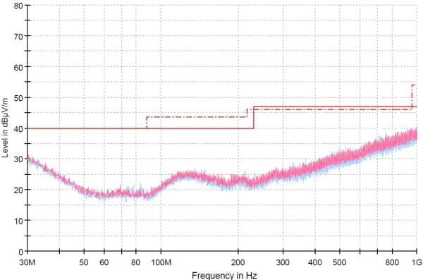
Anechoic Chamber Ambient Plot
The final result was indistinguishable from the noise floor of the chamber, which was the goal.
This method of choosing a higher performance off-the-shelf supply is used very commonly. For example, if you have an application where you must meet class A FCC limits, you could have a class B power supply as backup, which in theory has higher performance by at least 10dB. But as I’ve shown here, even power supplies/drivers of the same grade can have widely varying performance.
Effect of active harmonic suppression
Another consideration for your LED lighting is whether it needs to meet flicker & harmonics requirements. In Europe, under the CE Mark, this is covered by EN61000-3-2 and EN61000-3-3. Typically this applies to electrical equipment with power draw over 75W (many caveats apply).
In US under the FCC’s rules, this is not a mandatory requirement although it may be called out by an international product standard that your product must adhere to.
The flicker & harmonics standards are an effort to minimize wasting power drawn from local and regional power distribution systems. Effectively it’s a limit on the amount of distortion that your equipment can cause to the sinusoidal AC input voltage waveform.
As part of this case study, I bench-marked the LED floodlight against a similar product.
It became apparent quite quickly that the other product did not have active harmonic suppression. The power factor and total harmonic distortion were much worse and it failed the harmonic current test. Whereas using an LED driver with block diagram similar to the one shown at the start of this article allowed for a much better power factor and THD performance. Comparison of the results between the two products shown below:
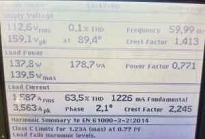
Similar Product Without Power Factor (Harmonic) Correction – Failed
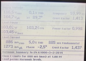
Case Study LED Light With PFC – Pass
These measurements were taken using a flicker and harmonics analyzer (HA1600A) from TTI Instruments.
Summary of methods to minimize EMI from LED lighting
While our hands are somewhat tied when using an off-the-shelf power supply or LED driver, there are some things we can do to minimize emissions.
- Evaluate 2 or 3 different drivers from different vendors. Performance varies significantly.
- Turn off PWM if your design constraints allow.
- Apply a general purpose AC filter to the input of the power supply.
- Apply ferrite(s) to the input power cable. Ensure ferrites are appropriately current rated to avoid saturation and select for maximum resistive attenuation at the problem frequencies.
- Ensure maximum physical clearance between the driver input cable and output cable to minimize the coupling between those cables (high coupling between input/output cable can reduce the effect of filtering).
- Ensure the driver housing is well bonded to the chassis of the product very near to the power cable penetration to minimize common mode current on the cabling.
- If you need to pass flicker/harmonic tests, ensure your LED driver has power factor correction (CE Marked supplies should have passed this).
Conclusion
This was a simple case study about reducing EMI from a 100W LED floodlight when using an off-the-shelf LED driver. If you would like more in-depth training on low EMI (radiated and conducted) power supply design, check out the EMC Design for Compliance: Emissions online course.
Comments 17
Another great example, thanks! Amazing to see how much each driver varies at test. I have found that comparable PCB filter components do this as well.
Author
Thanks Nick. An equivalent filter comparison would be another good subject! I’ll add it to the list 🙂
Hi Andy, thank you, that was a pretty interesting read, I stumbled across this while Googling the problem I have been trying to fix, it’s an articulating led bench lamp/magnifier I have on my bench at work. It makes a hum on my audio amplifier, and worse the closer it gets to the amp.
Perhaps you can answer a puzzling thing that happens please.
When I hold any metal part of it, like the metal arm, the noise through my speakers almost completely disappears. So I thought I could just modify it by adding an earth ground, I even replaced the cord with a 3 wire ac cord.
I tried a clip-on ferrite, nothing helps, I even tried jumping the ground to the arm of the light.
I tried making a “macgyvered” a Faraday cage around the switching power supply.
It seems the only remedy is me holding it, holding the ground, or the plastic cover of the supply, that works even when I am not touching the concrete floor. I would have thought that I was acting like a filter capacitor for the ground, and that a direct ground would be better, but that’s not the case.
Any thoughts on what I’m experiencing, or remedies ?
I guess last resort is replacing the supply like in your experiment.
Thank you
Paul
Hello Paul,
Encase the Driver or PS in a sheilded box and earth it as you have done,
Add a gap between the driver of the LED Section away from the case, Thermal pad ??
Check your Earth is 100% solid all the way to the distribution board,
the fact that is goes away when you hold it shows a resistance to earth, is in play, then check for EMI induced inot the LED by the driver….
Agree !!
Hello Paul,
Encase the Driver or PS in a sheilded box and earth it as you have done,
Add a gap between the driver of the LED Section away from the case, Thermal pad ??
Check your Earth is 100% solid all the way to the distribution board,
the fact that is goes away when you hold it shows a resistance to earth, is in play, then check for EMI induced inot the LED by the driver….
Such a detail and well-explained about LED lighting EMI comparing to others I have read. Ande Eadie deserves to get a A++ as myself, an EE viewpoint. Also thanks to FASTTRAK editor’s insightful selection of author.
Author
Thanks Jonas. I’ll let the editor know 😉
I enjoyed this reading. Very informative, well done!.
Author
Thanks Richard.
Hi Andy, nice article and I specifically like the way you broke down the steps so people can follow your thought process.
Just one tiny Niggle, I have to disagree with you saying test labs are expensive. Our lab in Reno ( SSCLABS ) has two 40+ NARTE engineers running the tests for less than the cost of a consultant.. I hope we can tempt you to visit someday. The kettle is always on.
Keep up the good work!!
Hi!
I can’t hit the answer with google. Please help. 🙂 Could coaxial cables (2 – only their cores for power) be used as solution to EMI of led powering?
It’s a common tip: use shielded cables to power leds if you have EMI issues. But, coaxial cables seem a good example of shielded cables.
They are thick and don’t bend too easily, but it’s easy and cheap to buy one with copper foil and copper mesh shielding, which suggest strong EMI protection. Typicaly from external sources. Why not protect external sources from interference of current flowing inside the core of coaxial?
This is very practical advice for cleaning a switch-mode power supply for any application so thank you.
However I’m specifically interested in how much EMI is emitted by the diode module itself. Assuming a completely flat DC power source, how much noise is created by the reactance of a high-powered diode body and how much of that is radiated, and if so what can be done to mitigate the effect? Suppose I want a bright LED on a circuit board next to EMI sensitive components?
Pingback: Self-Build EMC and Microwave Chambers - EMC FastPass
I read your article and found it very informative. I have a repurposed building that has eight 24″ led fixures an three standard led bulb fixures. The problem is with my radio equipment picking up interference when these lights are energized. Where would be a good starting point at locating parts for a fix?
Very nice information. Thanks for explaining led lighting so nicely here. When it comes to led lights, there are so many options available. The above information was great.
Such a great and detailed test!! I know I may have missed it, but is it possible to find out the exact drivers/products you were using? I’m currently working on a project where I need to have a medium sized array of LEDs in pretty close proximity to guitar pickups/circuits so noise is big problem for me right now, which led to a lot of searching online…and ultimately brought me here!! I was able to very easily follow your tests and explanations so I was just curious about the exact products you were testing (primarily…the one that ended up being better!), so that I could try ordering one and applying those various modifications too. Thanks again for the great test!!