If you’re considering an anechoic chamber (some call it an EMC chamber) for in-house emissions, immunity or wireless testing, this guide will help you to determine the important factors to consider when you’re choosing a make and model. But even if you’re not in a position to purchase a chamber, this guide will help you to understand more about the chamber at your 3rd party testing provider’s facility.
Here are some of the topics we’re going to cover in this post:
- What are anechoic/EMC chambers and how do they work?
- What types of EMC chambers are available and how do they differ?
- What are the design characteristics of an EMC chamber and how do they affect performance?
- Typical test equipment required for radiated emissions testing and radiated immunity testing in a chamber
- EMC chamber costs: new vs. used
- Used EMC chambers for sale
- Dismantling, re-assembly and transportation costs
EMC Chambers – What Are They And How Do They Work?
The word ‘anechoic’ more or less means ‘without echo’. The first part of the word ‘an’, meaning ‘not’ or ‘without’ and the second part ‘echoic’ coming from the Latin word echo which itself stems from the Ancient Greek word ἠχώ (ēkhṓ) and the related word ἠχή (ēkhḗ, “sound”).
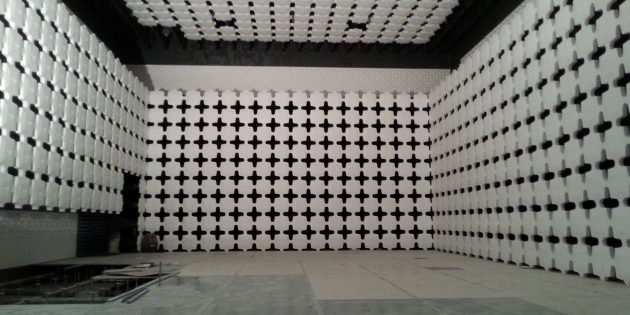
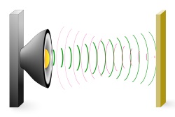 The key characteristic of an anechoic chamber is that it’s designed to absorb reflections of waves within the chamber rather than have them bounce off the walls which would cause an echo. These chambers, if designed and assembled correctly, also do a great job at keeping waves from entering the chamber i.e. they provide shielding from outside interference.
If you’ve ever been in a huge room or cave and shouted ‘echo!’, you’ll know that you usually get some kind of reverberation where you hear your voice repeat a few times.
To avoid this phenomena, anechoic chambers are lined on the inside with materials that absorb waves (which we’ll get into below).
There are many types of anechoic chambers that are designed for different applications. Some of the most common uses and types are for things like audio recording, radiated emissions testing, radiated immunity testing, wireless transmitter (RF) testing, antenna testing and specific absorption rate (SAR) testing.
Audio chambers are the odd man out here because they deal with absorption of sound waves rather than electromagnetic energy which is common to all of the other types of chambers. In this guide we’ll be dealing with electromagnetic (EMC/EMI) anechoic chambers.
What Types of EMC Chambers Are Available?
In terms of electromagnetic testing, which is of course my focus here at EMC FastPass, there are a few different types of chamber that can be super useful. Your choice really depends on your application (and also the size of your wallet!).
Semi-Anechoic Chambers (SAC) vs. Fully Anechoic Room (FAR)
The most common type of EMC testing chamber by far is the semi-anechoic chamber. The word ‘semi’ indicates that it’s only partially able to absorb electromagnetic energy and one of the reasons for that is that the floor of the chamber is reflective rather than absorptive. Why is it reflective? For a couple of main reasons:
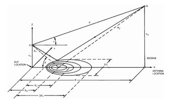 A reflective floor (usually a sheet metal ground plane) simulates the real world more closely compared to a free space measurement. Remember that radiated emission limits are an attempt to limit the amount of interference your product can cause to another product or transmitter. In the real world, a product will usually ‘see’ an electromagnetic wave in direct line of sight, plus a reflected wave off the earth or nearby walls (see diagram to the right). The reflective ground plane in a semi-anechoic chamber mimics a real life scenario much more closely.
- A reflective ground plane helps to make radiated emissions measurements more repeatable and accurate. Why? Because RF absorbing material is not perfect. Its performance varies with frequency and also varies with the incident angle of the wave. So if your product emits electromagnetic radiation at different frequencies (which it does) and at different angles (which it does), then the amount of absorption (measured in dB) will be slightly different for each emission.So when the receiving antenna receives the signal, it’s tough to know exactly what compensation factor to include due to the imperfect floor absorption. With a reflective ground plane, the reflected energy at all frequencies of interest is much more uniform and therefore easier to predict.
But, that isn’t to say fully anechoic rooms (FAR) don’t exist. An effort has been underway for many years to develop and adopt a standard for making repeatable measurements in a FAR (such as that outlined in EN 50147-3).
One of the reasons for the push is that if measurements made in a FAR can be proven to have good correlation to an OATs (see below) or a SAC, then there could be significant cost savings to be had. The cost savings relate to:
- The ability to make measurements in a much smaller chamber (making large savings on expensive absorber material)
- Reduced test times because the antenna height would not have to be scanned between 1-4 meters (which is the case for SACs and OATS due to the maximization procedure required to compensate for the reflective ground plane)
- Reduced facility cost due to automated antenna mast not being required (usually at least $10k)
You may also need a fully anechoic room if you’re attempting to remove all reflections for transmitter/receiver testing, which helps to remove multipath artifacts. It’s a lot easier to create a FAR for a specific transmitter because you’re predominantly interested in absorbing a very tight band of frequencies.
So, the quest for a lower cost FAR test chamber exists, but studies have highlighted repeatability issues as well as correlation issues to measurements made at the more trusted SAC and OATS test facilities.
Semi-anechoic chambers and OATS are the preferred method for almost all radiated emissions testing standards such as the ubiquitous ANSI C63.4 and CISPR 16.
Semi-Anechoic Chamber vs. OATS (Open area test site)
The standard choice for in-house or 3rd party emissions testing facility is either a semi-anechoic chamber or an open area test site (OATS).
In many ways the OATS is preferable to the SAC because there are no walls in the vicinity of the measurement area. Even with plenty of absorbing material on the walls of a SAC, there will still be a portion of the wave energy that gets through the absorber and reflects back off the metallic surface of the chamber wall. The receiving measurement antenna in that case picks up the wave coming from the equipment under test (EUT), the reflection off the floor, and the partial reflection off one or more walls.
So it can be harder to achieve acceptable measurement accuracy (typically +/- 4 dB according to ANSI C63.4) in a SAC than it is at an OATS.
The main downside of an OATS of course is that since there is no shielded chamber, the measurement antenna also picks up whatever is floating around in the air at the test site. That can include things like the FM radio band, cell phone bands, air traffic, maritime radio, emergency services and much more. That background noise (called ‘ambient noise’) often makes it hard to see the emissions coming from an EUT so testing usually goes a lot slower compared to testing in a SAC.
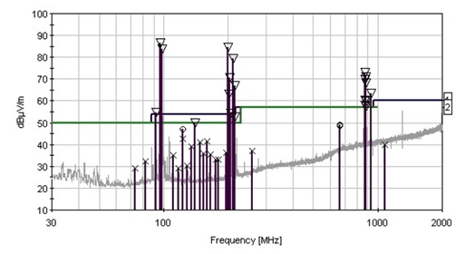
Signals from EUT plus ambients measured at an OATS
The ambient noise problem gets worse the more transmitters you have in the vicinity, so within or near a large city it makes testing on an OATS next to impossible. The ambient noise also prevents automated emissions testing because human intervention is required to distinguish between noise from the EUT and background noise. Long story short – testing at a SAC goes much faster.
The other downside of an OATS is that you can’t legally perform radiated immunity testing because it’s illegal to broadcast at the power levels typically required to generate the field strengths called out by the RI root standard (IEC 61000-4-3) e.g. 3 V/m, 10 V/m or higher for MIL/aerospace. So if you want to do radiated immunity testing as well, you’re going to need some kind of chamber (ideally a SAC, but there are other options which I’ll discuss below).
Semi-Anechoic Chamber vs. GTEM
A poor man’s SAC is a GTEM which stands for Gigahert Transmissive Electromagnetic cell. These are much smaller than a SAC and much more cost effective, but they have their limitations.
I went into detail on GTEMs in previous articles here and here.
You can legally use GTEMs to measure radiated emissions for FCC part 15B and 18 devices (with some caveats) and perform radiated immunity testing according to IEC61000-4-3 appendix D. In terms of radiated emissions testing, IEC/EN61000-4-20 outlines the usage and restrictions of a GTEM for testing purposes.
The two main downsides of a GTEM are the limited EUT size and the measurement error at lower frequency ranges (approximately under 200 MHz). Measuring emissions coming off cabling, which is a dominant failure mode due to common mode currents, can be really tricky in a GTEM. This paper outlines the effects of different cable configuration on measurements within a GTEM.
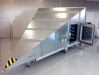
GTEM Cell [Wikipedia]
To compensate for the increased measurement uncertainty at frequencies below 200 MHz, I would advise using a current clamp as well to measure the common mode current present on every cable in the 30 MHz – 200 MHz frequency range. In that band, most of the radiated emissions failures are due to common mode current on external cabling, so between the GTEM and the cable clamp, you’re going to be able to find and quantify absolute emissions levels quite accurately.
A SAC is definitely preferable to a GTEM, but if you have space and/or budget concerns, a GTEM might be a better way to go. Some companies have both, reserving the GTEM for pre-compliance testing and the SAC for full-compliance testing.
A good app note from Nokia compares measurements from a GTEM to a SAC to an OATS. And York EMC have another excellent app note on GTEMs here.
Reverberation Chamber
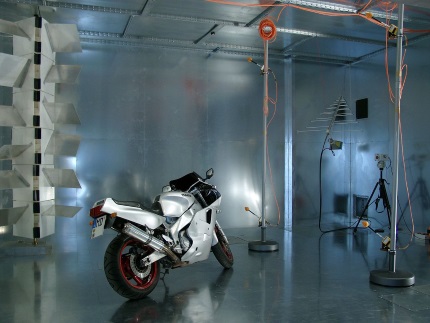
[Wikipedia] Reverberation Chamber at the Otto-von-Guericke-University Magdeburg, Germany
Power amplifiers can easily cost tens or hundreds of thousands of dollars, especially if you require the high field strengths called out by standards such as MIL-STD-461 and DO-160 (200 V/m). In contrast field strengths of tens of thousands of V/m can be produced in a reverberation chamber.
In one of these things it would be pretty easy to exceed the RF exposure guidelines set out in the FCC’s OET65 (Human exposure to RF EM fields) so I wouldn’t recommend walking into one while it’s on if you ever plan on having kids.
Reflectors like the ones shown in the picture are used to ‘stir’ the standing waves so that all points of an EUT can be immersed in a field of a given strength.
RF Shielded Room
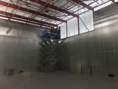
Shielded Chamber – The Basis for a Semi-Anechoic Chamber
An RF shielded room forms the basis for a semi-anechoic chamber. It’s a well sealed metal box, that offers electric and magnetic field shielding effectiveness over a given range of frequencies.
This picture on the right is from a 10m chamber that I bought and dismantled earlier this year.
There are of course different shielding materials and configurations, which carry with them different shielding performance. Factors such as the material type and thickness affect electric and magnetic field attenuation as you can see in the table below.
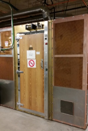
Screened Room
Sometimes copper mesh is adequate, as in the case of a ‘screened room’ (like the one shown on the right). If you only need 50 or 60dB of attenuation, these will save you a lot of money compared to a full shielded room.
If you need maximum shielding effectiveness, you’ll want ‘double electrically isolated’ shielding, which has two layers of shielding material (one on the inner surface and one on the outer surface), typically connected at only one point – the main grounding point.
RF Shielded Box/Chamber
Inquiring about the cost of a full size semi anechoic chamber, for many manufacturers at least, often induces mild heart palpitations.
Engineers searching for alternatives may come across a small shielded enclosure (e.g, 2ft x 1ft x 1ft) and wonder what’s stopping them from using that for emissions or immunity testing instead.
One of the main issues with these shielded boxes is reflections. The physical size will limit the dimensions of the absorbing material and therefore it won’t be possible to fit absorbing cones in that are very effective at lower frequencies.
Also, with such small dimensions, you’ll be measuring or transmitting in the near field for any frequencies under a couple of GHz.
Both of these factors lead to measurement of unintentional emissions being pretty useless.
![Faraday Cage Electron Movement with Applied Electric Field [Wikipedia]](https://emcfastpass.com/wp-content/uploads/2016/06/faraday_cage.gif)
Faraday Cage Electron Movement with Applied Electric Field [Wikipedia]
- Wireless transmitter/receiver testing – the shielding provides a relatively noise free area where wireless communications links can be tested in isolation. If you know the transmitter frequency, the absorber material can be chosen specifically to absorb energy at the transmission frequency.
- Radiated immunity testing – don’t expect the same performance as a stable, calibrated, uniform field that you would expect from a proper test setup in a semi-anechoic chamber. But it’s possible to feed in a signal to a small antenna and create a significant field strength without violating laws around unlicensed transmissions on restricted frequency bands. Might be useful for radiated immunity troubleshooting.
- Making sensitive measurements – these boxes can provide >100dB shielding effectiveness above 1 MHz, so if you need a noise free environment to test your circuit or even for your circuit to operate normally, then these RF shielded boxes can be a good solution. Note that on their own, the boxes will only reduce the radiated coupling mechanism. Proper cable filtering will be needed to reduce conducted coupling from external sources (e.g. via power or ground signals). Of course electric and magnetic field coupling can still occur between aggressors and victims within the enclosure itself.
Using an EMC Chamber for RF (Wireless) Testing
Let’s not forget that a semi-anechoic chamber isn’t just useful for emissions testing. With the right types and configurations of absorber material, it’s perfectly acceptable to do RF transmitter testing, either for transmitter characterization (such as emissions bandwidth, power spectral density and spurious emissions measurements), but also for testing links between 2 or more transmitters.
Antenna Measurement Chamber
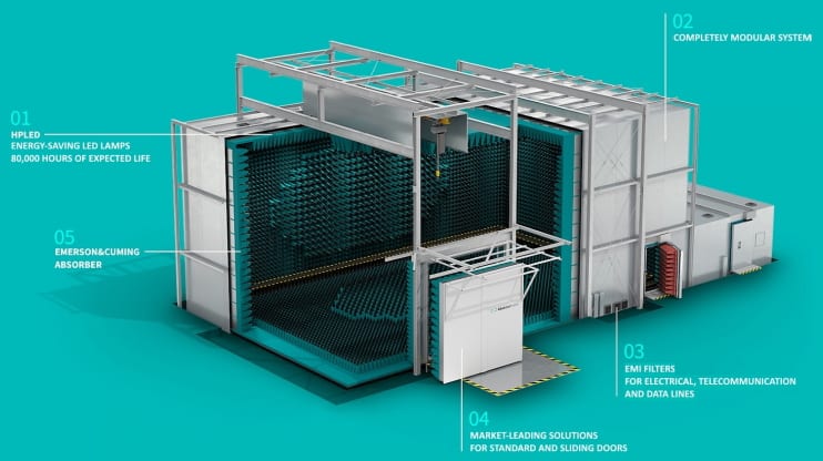 There are special types of anechoic chambers designed specifically for characterizing the field patterns from antennas. While I think it’s possible to make antenna pattern measurements in a standard semi anechoic chamber, a specialized antenna measurement chamber is likely to provide more accurate data along with faster scan times.
Something like the antenna measurement chamber shown on the right shows an example of a modular antenna measurement chamber with a full treatment of hybrid RF absorber.
We sometimes have used antenna measurement chambers for sale. Check out our online store for current inventory.
Semi-Anechoic Chamber Variables
Antenna Separation
One of the main considerations with a semi-anechoic chamber is the physical distance between the EUT (equipment under test) and the measurement antenna.
Near Field vs Far Field
 For RF emissions and immunity testing purposes, separations of 3 meters, 5 meters and 10 meters are the most common.
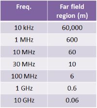
Freq. vs. Far Field Distance
The separation is important because it defines the frequency at which you transition from measuring within the near field to measuring within far field.
Ideally you always want to measure in the far field because it’s only at that point that any wave is setup as a plane wave.
In the near field, the field strength may diminish at 1 over r cubed or r squared and may vary wildly between 2 points (where r is the separation between the source and the antenna). In the near field, the behaviour is very much dependent on the source of the emission. If it’s high dV/dt, the near field will be predominantly E-field. If it’s high dI/dt, the near field will be predominantly H-field.
Whereas in the far field, the field is stable and diminishes quite predictably at 1 over r.
Antenna Separation by Standard
Often particular standards mandate a specific separation distance, but will allow you to use different separations by extrapolating the limits to the new separation. For example, in the Industrial, Scientific and Medical standard CISPR 11, allowable separations vary depending on the size of the EUT as well as the class (A or B) and the group (1 or 2).
A larger separation is generally considered to be more accurate because it’s more likely that you’ll be measuring in the far field rather than the near field.
3m separation would be my recommendation for minimum separation for radiated emissions testing in the 30 MHz – 1 GHz range.
Antenna Separation for RF Antenna Measurements
If your chamber is for antenna measurements, the separation between the AUT (antenna under test) and the measurement antenna will be guided by your transmission frequency and the size of your antenna. If you’re transmitting at 2.4 GHz, 1 wavelength is only 12.5cm, so you can get away with much smaller separations (and much smaller anechoic chambers).
Some chambers use a reflector to increase the measurement distance within a fixed chamber size to get closer to a far field measurement.
Frequency Range
The next thing to consider is what frequencies you need to measure within your chamber.
Chambers are fairly well known to not perform very well at lower frequencies (e.g. below 100 MHz) due to limitations to pyramidal absorber length (discussed in more detail below). That’s why it’s often a good idea to re-measure the lower end emissions on an OATS.
But you can really affect the upper frequency range by your choice in absorber materials and also the effectiveness of the shielding.
- Radiated emissions testing
For RE testing of unintentional radiating devices, you’ll typically want to measure from 30 MHz up to several GHz, with the upper limit depending on the highest frequency present in your design.

Unintentional Emissions Measurement Range – FCC 15.33
The FCC defines the upper measurement range for unintentional emissions measurements, which as you can see from the table above depends on the highest frequency generated or used in your design.
- Radiated immunity testing
For RI testing, you’ll typically want to go from 80 MHz up to 2700 MHz. Your standard may define higher or lower values than this, but for many devices, 80 M – 2.7 G is typical. Expansion to 6 GHz is planned for some standards, so it may be prudent to design your chamber up to at least 6 GHz if you plan to undertake radiated immunity testing.
- RF spurious emissions
For RF (or wireless transmitter) testing, it’s often required to measure spurious harmonic amplitudes up to the 10th harmonic. E.g. for a 2.4 GHz transmitter, you’ll need to verify all harmonics up to 24 GHz are within compliance.
The FCC mandates measurement of spurious emissions from Part 15 wireless transmitters up to the 10th harmonic
Semi-anechoic chambers often come specc’d up to 40 GHz, but you can go higher or lower depending on your requirements. This will typically affect your choice of absorber material.
Quiet Zone
The “quiet zone” characteristic defines an area within your chamber that your EUT must fit within, if the measurement accuracy characteristics are to be met. The larger the EUTs you want to accommodate, the larger your chamber needs to be to maintain measurement accuracy.
As you can imagine, increasing the quiet zone means you need to increase your chamber width (and possibly length and height) which increases amount of expensive absorber material to line the walls.
Choosing Absorber Material
The RF absorbing material that lines the inside walls of your chamber is crucial to the overall performance. Its goal is to absorb 100% of any incident electromagentic waves and convert that energy to heat.
In reality all absorbing materials are not perfect at absorbing RF energy and their performance is very dependent on a number of factors such as the incident angle of the waves, the frequency and the power levels. Reflections will occur, but your choice of absorbing material will define how bad the reflections are and how much energy is absorbed.
Ferrite Tile
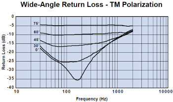
Ferrite Tile Absorption vs. Freq and Angle
Ferrite tile typically lines all of the walls and ceiling of an anechoic chamber. Ferrite works best at lower frequencies (e.g. below 100 MHz) and it works in combination with hybrid absorber foam (see below) to minimize reflections over a wide band of frequencies.
Looking at the absorption profile of a typical ferrite tile, you can see that it’s fairly useless if the incident angle of the wave deviates from normal by any significant degree.
The tiles are usually mounted onto a piece of wood before being screwed into the chamber’s shielding panels. The wood spacer actually acts as a dielectric spacer between the tile and the grounded wall panel, creating a capacitive effect.
Sometimes for emissions pre-compliance chambers as well as immunity chambers, hybrid absorber won’t be required on top of the tile. It really depends on the upper frequency range of the signals you want to measure.
Also, you can get away with less than full coverage (specular coverage) at the cost of measurement accuracy. Ferrite tile is one of the most expensive components in a chamber, so if you don’t need a fully compliant room, this may be a good area to save money.
Absorber Foam
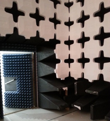
2 Types of Pyramidal Hybrid Absorber
If your EUT emitted only 1 frequency, it would be possible to absorb all of the wave energy with 1 sheet of paper coated with a substance of surface resistivity of exactly 377 Ohms (the wave impedance of free space), placed at exactly 1/4 wavelength from the reflecting wall (assuming the wave was incident at right angles to the wall). This configuration is called the “Salisbury Sheet”.
But of course, we’re trying to absorb a large band of frequencies at many incident angles, so we eventually end up with a tapered cone that absorbs different wavelengths of incident waves. Also, the pyramidal shape allows from a gradual transition of impedance from free space impedance (377 ohms) up to the impedance of the lossy ferrite tile absorber base.
Just as in the case of high speed digital design on a PCB, any sudden change of impedance will cause reflections, so the pyramidal structure is an attempt to minimize this effect.
This type of absorber can be made from a number of materials such as polyurethane or polystyrene, with either of these materials typically loaded with a lossy material such as carbon.
There are lots of papers on how absorbers work, but this one from Glen Dash is one of the best (i.e. most concise and easy to understand) I’ve found.
Cable Filters
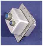 To be able to maintain excellent shielding effectiveness, everything entering or exiting (penetrating) the walls or floor of an anechoic chamber must be filtered or isolated.
That includes everything from the power supply input for the EUT and turntable/mast, RF cables (connecting to the antennas or LISNs) and any other I/O and control cables.
If you just fed the cables through a tight hole, the chances are that RF leakage would occur in both directions. The effect of that is that you would begin to see ambient RF signals within the chamber when the whole purpose of a chamber is to keep them out.
The amount of RF leakage you’ll get, or the amount of reduction in shielding effectiveness, would depend on the dimensions of the hole or aperture, the wavelength of the signal that encounters the hole, and whether the source is in the near or far field.
Doors
Credit: Learnemc.com
The doors used to enter and exit an anechoic chamber are a common area where the shielding effectiveness can be weakened.
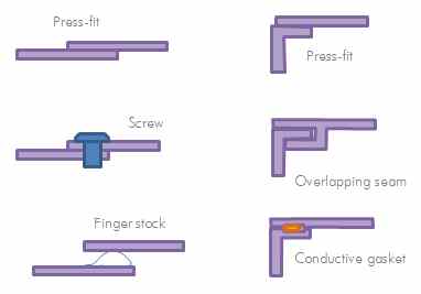
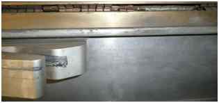
Since it isn’t possible to have a perfect press fit of metal to metal around the door, finger stock (shown below) is the preferred method to ensure that there is a tight seal the whole way around the door.
Measurement Accuracy
A crucial factor in determining the performance of your anechoic chamber is measurement accuracy. There are many factors that affect measurement accuracy to take into account:
- Antenna separation (are you measuring in the near or far fields?)
- Absorber material and placement (over what frequency range is your absorber material effective, what is the absorption loss at each frequency and where are the absorbers placed) – see below for more details
- What size is the chamber? – Is there enough space between the measurement antenna and the absorbing material?
- Antenna calibration (have your antennas been reliably calibrated?)
- RF cable calibration (do you know what calibration factors to include for RF cable losses at each frequency?)
- Spectrum analyzer/receiver calibration
For EMC pre-compliance measurements, you may be content with a measurement that’s +/- 6 dB accurate. Whereas for full compliance measurements, the typical required accuracy is at least +/-4 dB.
Relaxation of measurement accuracy generally equates to a lower overall cost of a chamber because you can use cheaper absorbing material or less of it.
Importance of Absorber Placement
Knowing which types, sizes and configurations of absorber to select is a tricky business. Typically this process is taken care of now by simulation software.
Usually a chamber needs to be fully lined with ferrite tiles (at least on the walls and ceiling), but it’s often possible to use only ‘specular anechoic’ coverage of absorbing foam material, whilst still meeting the +/- 4dB measurement criteria. To be able to determine which absorber material and size to pick, as well as where to place it, that’s determined by a number of factors including:
- How large of a quiet zone do you need?
- What is the largest EUT size you’ll be testing?
- What are the dimensions of the chamber?
- What frequency range will you be measuring over?
Your chamber manufacturer will likely offer several stock packages or use software to customize according to your requirements and budget.
Ground Plane Flatness
Ground plane flatness is essential for ensuring a repeatable reflection off the ground. In ANSI C63.7 (“Construction of Test Sites for Performing Radiated Emission Measurements”), the criteria or rule of thumb for ground plane flatness is called the Rayleigh roughness criteria which approximates that the ground plane should not have ‘bumps’ or ‘valleys’ exceeding 5cm at 3m antenna separation, to maintain measurement accuracy.
Using a flat, sturdy sub-floor beneath your metallic groundplane will help to ensure that the surface stays flat. Also the type and quality of welds or joints used to join together the metal sheets will have an impact.
It’s arguable that ground planes at an OATS are far more susceptible to warping due to expansion and contraction caused by direct sunlight than a chamber.
Sizing Your Semi-Anechoic (EMC) Chamber

Choosing the right size of semi-anechoic chamber is critical because it defines what measurement accuracy you can expect as well as which standards you can perform full compliance testing to.
EUT size
One of the main considerations in selecting your chamber size is the maximum size of the EUT you’ll be testing. If you’re testing small products, you can get away with a smaller ‘quiet zone’ as I discussed before, meaning the chamber width can be kept small.
Most chamber manufacturers quote the quiet zone dimensions for each of their standard chamber sizes.
Full vs. Pre-compliance
As I mentioned earlier, if you only need to make pre-compliance measurements, you can get away with a much smaller chamber. This allows you to make big savings on not only floor space, but also the cost of ferrite tile and absorbing materials.
ETS Lindgren has the ‘Spacesaver’ series for example, which are significantly smaller than their standard 3m, 5m or 10m chambers. Typically with small chambers like these, the antenna height will be limited or even fixed, which certainly limits the measurement accuracy. But, for getting a good idea of emissions, or troubleshooting known emissions problems, they can be a good option.
Definition in Standards
For many standards, the anechoic chamber size is not clearly defined. The litmus test is often whether the chamber meets the NSA requirements (see below) of the standard for a given EUT size.
But, in general a chamber sized to accommodate a 3m EUT to measurement antenna separation (e.g. approx 30ft x 20ft x 20ft) will be adequate for most international radiated emissions measurement standards.
5m separation is considered superior to 3m separation because the measurements generally have better correlation to measurements made at 10m separation (the gold standard of chambers). But of course as you increase the antenna separation, the amount of absorbing material lining the walls greatly increases which bumps up the cost.
Raised Groundplane vs. Pit
The maximum height of your chamber will be defined by not only the exterior chamber dimensions, but also whether it’s built on top of a pit. Typically an anechoic chamber will have at least 2 ft below the ground plane to allow for:
- A turntable with surface flush to the groundplane
- A place to store auxilliary equipment below the turntable
- A place to run antenna, power and other cabling
If you have the luxury of pouring a concrete pit, that’s great – the groundplane can be made to be flush with the rest of the floor (externally).
Other options are to build on top of a floor and have steps up to the chamber door, or in some cases, you can raise the whole floor of the room to bring it flush to the chamber floor.
These decisions are of course dependent on the constraints of the space you’re working with.
Typical EMC Chamber Performance Characteristics
You’ve probably gathered by now that chambers are far from perfect. To define how far from perfect they actually are, there are a couple of standard tests that determine two main aspects of their performance.
Shielding Effectiveness
The first is to determine how good the metal shell is at preventing RF signals getting inside. There are a number of areas where RF signals can ‘leak’ into the chamber, such as at panel joints, cable penetrations and doors.
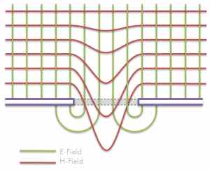 The shielding effectiveness is usually tested at 1 GHz (unless the customer requests a more in depth test at other spot frequencies) by placing a transmit antenna outside the chamber and a measurement antenna inside the chamber.
The difference between the transmit power and the receive power defines how effective the shielding is.
The diagram to the left shows how electric and magnetic near fields behave in proximity to a breach in the shield.
Pro-tip: to find the source of a leak, dial down the transmit power until the signal is barely perceptible inside the chamber. Then move the receive antenna around the chamber to find the maximum amplitude. This normally allows you to isolate the leakage area.
NSA
There is a publicly searchable database of every FCC listed/listed & accredited measurement facility in the world. For each facility, you can view their submitted data to see how the measurement accuracy varies with frequency.
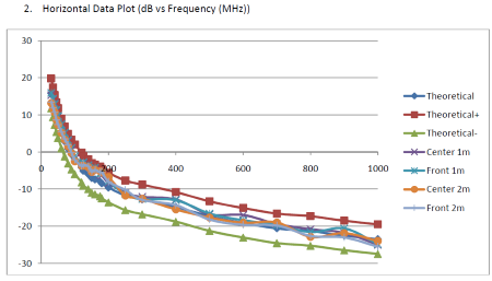
Normalized Site Attenuation Survey (NSA) Data
A dirty little secret of the EMC test lab industry is that even where labs meet the +/-4dB measurement accuracy specification, lab to lab variance can be much more than 8 dB. The FCC performs ’round-robin’ testing of EUTs around every lab involved in their TCB program. Statistics of the round robin are not published, but discussions in webinars by TCB participants indicate that variations of more than 40dB are not unheard of.
Often EMC test labs with more than 1 anechoic chamber will purchase an identical size, make and model of chamber so that internally at least, the chambers have good correlation. This helps them to avoid an awkward conversation justifying differences in measurements with their customer.
VSWR
The VSWR method has been used for decades to qualify characteristics of anechoic chambers such as the size of the quiet zone and the reflectivity of the absorbing material. Some also prefer the VSWR method to the NSA to characterize measurement accuracy.
Although there are many ways to perform a VSWR test, most are variations of a method based on moving a transmitting source along a measurement axis to sample a standing wave of an electromagnetic field.
Check out this and this for more information.
Typical Equipment Required
Now that you have your semi-anechoic chamber, what else do you need? Unless you like sitting in a very quiet room, listening to nothingness (or in my case some very loud, high pitch tinnitus), you’re gonna need some gear to make the most of the space.
What you’ll need depends on the testing you want to do in there, but below I’ll outline the main pieces of gear for emissions, immunity and RF testing.
Radiated Emissions Testing
- Antenna(s)
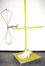 The type of measurement antenna you get really depends on what frequency ranges you need to measure. I outlined the various types of antennas used for EMC testing in the radiated emissions section of the EMC testing beginner’s guide. Typically though, you’ll be looking at a biconical antenna for sub 300 MHz, a log-periodic antenna from 2 or 3 hundred MHz up to 1 or 2 GHz, then a horn antenna for >1 GHz.
Many labs use a biconilog/bilogical antenna which is a combo of a biconical and log period, to cover a larger range with only one antenna.
- Spectrum analyzer/EMI Receiver
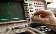 The other main piece of equipment you’ll need is either a spectrum analyzer or EMI receiver. These two pieces of gear essentially do exactly the same thing i.e. they measure the voltage picked up from the measurement antenna across a range of frequencies. However the receiving circuitry inside them is really different, giving them each pros and cons.
If you want to do full compliance testing, you’ll typically need an EMI receiver (CISPR compliant). For all other testing, a much lower cost spectrum analyzer equivalent will most likely suffice.
- Cable
Choosing the right RF cable is critical. Select one with low loss all the way up the highest frequency of interest. Since cable losses vary proportionally with cable length, you’ll want to factor in how far your receiver is from the antenna when working out what magnitude of cable attenuation is acceptable.
- Emissions automation software
You’ll most likely want some kind of automation software to (a) add/subtract factors for antennas, amplifiers, attenuators and cables (b) speed up testing (c) produce professional looking test reports.
See RF section below for more suggestions and information.
Radiated Immunity Testing
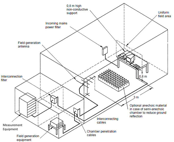
Test Setup From 61000-4-3
Radiated immunity testing uses mostly the same equipment as radiated emissions testing, with only a couple of additions.
- Antenna(s)
You can use exactly the same antennas (e.g. hybrid, horn) as used for radiated emissions testing, only they are driven hard rather than used in receive mode. The only caution here is to ensure that your antennas can handle the power levels that you need to drive to generate the field strengths called out in the applicable standards.
If your antennas aren’t up the job, you’re gonna have an expensive day.
- Signal generator(s)
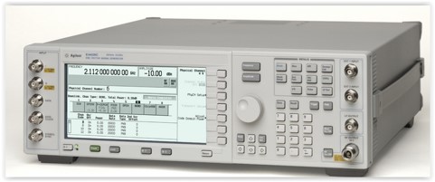 The signal source for the radiated field is always a signal generator. For standard radiated immunity testing according to EN61000-4-3, the signal is typically swept from 80 MHz up to a few GHz. The carrier frequency is a sine wave, and the signal is usually amplitude modulated with a 1 kHz signal (80% AM). These parameters can change depending on the standard, so check yours to determine the spec of signal generator you’ll need.
Sometimes it’ll be necessary to swap out a signal generator mid way through radiated immunity testing to accommodate a different frequency band. If you want to get really fancy, you can buy GPIB controlled switches and invest in good automation software to deal with signal generator and power amplifier swapping automatically.
- Power amplifier(s)
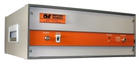 Power amplifiers are necessary to generate the power levels required to drive antennas hard enough to create the field strength levels called out in the standards.
For example, you might need a 50W amplifier to achieve 10 V/m at 3m across the 80 MHz to 1 GHz band. The power of amplifier you need is very much dependent on the specifications of your antenna (i.e. gain, VSWR) as well as the attenuation in the cabling.
- Automation software
Again, automation software is pretty necessary for any kind of radiated immunity testing other than troubleshooting at specific spot frequencies. For radiated immunity automation, the software needs to store the amplitude settings for the signal generator that correspond to a given field strength at a fixed distance from the transmit antenna.
Using an isotropic field probe, the software can calibrate the field levels across a band of frequencies and store those “sweeps”. Any changes to your test setup after calibration will probably totally nullify your calibrated field. That includes changes to: in-line atteunuation, antenna separation/orientation, RF cable type/length and basically anything else involved in generating the field.
- RF switches
RF switches aren’t necessary, but if you want a really smooth and fast setup then they’re a good option. They allow the automation software to select between different signal generators and/or power amplifiers so that you can sweep the whole frequency range without having to manually switch over cables and equipment. If you’re doing lots of RF testing, it could be worth the investment.
- Attenuators
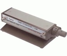
Variable RF attenuator
Attenuators are useful for a couple of reasons:
- It’s always a good idea to insert an attenuator between a signal generator output and a power amplifier input. If your generator output has a maximum output level of +10 dBm and your amplifier input has a maximum input level of 0dbB, you’ll want a 10dBm in series at the least. S.Gs have an uncanny ability to switch on at full power even when you swear you turned it down before you turned off the unit. A cheap attenuator can save you an extremely expensive afternoon.
- The EN/IEC 61000-4-3 radiated immunity standard requires that the amplitude of any spurious or harmonics of the power amplifier is at least 6dB below the fundamental output amplitude. Attenuation may be required to minimize cable reflections from the antenna and to keep harmonic amplitudes acceptable at the power levels required to meet a given field strength. This issue gets more important, the closer you get to the maximum power output of your amp.
- Isotropic field probe
An isotropic field probe is necessary to confirm that you’re generating adequate field levels at all locations within the test volume. If I remember correctly, the field levels (measured in V/m) are calibrated by measuring at 0.5 m intervals within the test volume (e.g. 1.5 m cubed), with acceptable levels being defined at between -0dB (i.e. can’t be lower than specified)/+6dB at not less than 75% of measured grid points (e.g. 12 of 16).
These days, the standard necessitates that the field is quickly verified at one point before each EUT is tested which ensures that you didn’t do anything daft with the cables, connections or software.
RF (Wireless) Testing
Before you even think about investing in a radiated wireless test set up, make sure to check out how useful conducted RF testing can be. It’s so much cheaper (<$5k as opposed to >$100k for a chamber) and covers 90% of the RF tests that you’ll need to do.
For wireless testing, you’re probably going to need some additional hardware:
- Antenna(s)
The type of antennas you need very much depends on the frequencies you need to measure. One hybrid broadband antenna can cover the frequency range 30 MHz up to a couple of GHz, but you may need to go higher and lower than that band.
Often you’ll need to measure spurious radiated emissions up to the 10th harmonic of your fundamental transmission frequency, in which case you’ll need at least one horn antenna.
- RF Amplifier(s)
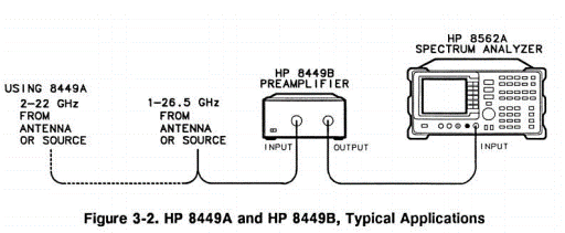
When you’re measuring low level radiated emissions, often you’ll need to boost the signal received from the measurement antenna to elevate the signal above your analyzer’s noise floor.
- Attenuators
Conversely to amplifiers, attenuators help to ensure that input signals meet the input requirements of your analyzer. In the case of a spectrum analyzer, that typically means saturation of the sensitive diode mixer circuit on the input.
If you do overdrive your analyzer’s input, the best case scenario is that you get some gain compression which results in inaccurate measurements. Worst case scenario is that you toast something expensive on the input stage.
Either way, it’s a good idea to add enough attenuation on the input signal path to ensure that your analyzer input stays within the specified operating range.
It’s usually better to use external attenuation rather than rely on the attenuators internal to your analyzer, for a couple of reasons. The first is that you can size your external attenuators to have an increased ability to dissipate power. Internal attenuators are usually very limited in their power handling capability, so without carefully calculating the powers involved, it’s relatively easy to cook them.
The second reason that it’s usually better to use external attenuators is that the noise floor will ‘appear’ to be lower. If you use internal attenuation, the spectrum analyzer will compensate by adding the attenuation value to not only the signal but also the noise. So, if you’re trying to measure a weak signal, internal attenuation may swamp the reading. With an external attenuator instead, the signal will be attenuated, but the noise floor will remain the same on the analyzer screen.
- Automation software
Automation software is typically necessary to store and compensate for transducer and amplifier factors. Without compensating for these factors, you won’t be able to calculate the absolute magnitude of the signal.
Automation software also allows you to generate a nice test report with a plot and tabulated data. To use automation software, you’ll need to connect your PC to your analyzer, which is usually accomplish via a GPIB communications port. PCI cards are available from National Instruments to give your PC a GPIB port. External USB to GPIB converters are available, but I could never get mine to work.
Manufacturers such as Rohde & Schwarz and Keysight (Agilent) often package their own automation software with their equipment. Typically it costs a fortune and there is an annual support fee.
Alternatively, you might want to investigate a free option called EMCware from Amplifier Research.
You could also perceivably write your own software in Labview or even excel. There’s a GPIB toolkit from KE5FX that could be useful if you want to go that route.
Anechoic Chamber Costs – Used vs. New (and some cautions)
There’s no getting around the fact that buying a semi-anechoic chamber is an expensive proposition. For larger companies it can be a no-brainer in terms of ROI, but for smaller to medium sized hardware companies, the decision to buy one and train up staff vs continuing to use a 3rd party test lab isn’t an easy one.
Occasionally you’ll find a used chamber for sale, and they often represent a huge saving.
Due to the high cost of absorbing materials (tile and foam) and the increase in wall/roof area with increasing antenna separation, a 5m chamber is significantly more expensive than a 3m chamber and a 10m chamber is significantly more expensive than a 5m chamber.
But here’s a ballpark of what you can expect for pricing. These are for fully compliant chambers.
Antenna Separation New Used
3m $300k-$750k $250k-$450k
5m $500k-$1m $350k-$750k
10m $1m-$2m $500k-$1m
If you’re looking for used chambers, drop me a line and we can chat about your requirements.
Used EMC Chambers For Sale
If you’re looking for used anechoic chambers, navigate over to our test equipment store for current inventory.
We buy and sell new and used anechoic chambers.
Cautions With Buying Used Anechoic Chambers
So as you can see, there are great savings to be had if you find a used anechoic chamber for sale, but there are a few things to keep in mind:
- Shielding effectiveness may decrease after dismantling/re-assembly
- Absorbing material may decrease in effectiveness over time
- Correct re-assembly methods are critical to maintaining SE and accuracy
Ways in which your installer can screw up the shielding effectiveness:
- Doesn’t add copper wool and tape at each hat and flap joint
- Doesn’t clean shielding panel joints before inserting into structure
- Poor filtering of power and signal cable penetrations
- Doesn’t test shielding effectiveness after installation with the correct equipment
- Poor shield grounding
- Using worn, broken or annodized finger stock around doors
Ways in which your installer can screw up the absorption performance (affecting measurement accuracy):
- Choosing the wrong absorber material
- Mismatch between ferrite tile material and hybrid absorber
- Leaving gaps between ferrite tiles
- Incorrect placement/orientation of specular hybrid absorber
Dismantling, re-assembly and transportation costs
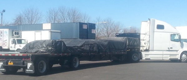
Part of a 5m Chamber Shipment
There are some additional costs to keep in mind if you’re purchasing a used semi-anechoic chamber.
Dismantling a chamber can easily take 5-30 days depending on the size and the amount of absorber/tile you need to take off the walls.
Pricing from professional chamber installers varies wildly, but expect to pay $25k-$100k to dismantle a chamber once all costs and equipment have been factored in and almost double those figures for re-assembly due to the extra time needed.
Transportation is generally via one or more large (53 ft) trucks or in some cases via shipping container. Expect to pay $1k-$5k for shipping costs per truck within North America. Also the amount of time it takes to load up trucks or containers can be very significant.
So even if you find a used anechoic chamber bargain, keep in mind that there are potentially significant costs for relocation.
New & Used Chambers for Sale
Check out my current inventory of used chambers. I’ve also partnered with a chamber manufacturer to be able to offer new chambers.
Conclusion
Ok that was a not so brief outline of several types of anechoic chamber. Did you find what you were looking for? Have any anechoic chamber experiences of your own to share? Let me know in the comments below.


Comments 32
Andy, your insight into the world of EMC is always much appreciated. This article brings together so many important topics of EMC chambers. Your cautions for used chambers is particularly useful. You do not disappoint, thank you.
Hey Nick. Cheers, glad it’s of use.
Thank you Andy. Very useful article. I wonder if it’s useful to do the test in EMC test house or at a factory where the equipment is actually built. Could you please highlight pros and cons of both?
Many thanks
Author
Hi Saif, try this article: https://emcfastpass.com/emc-test-equipment-guide/
It compares in house vs 3rd party testing costs.
Hi Andy,I am so excited and happy to read this. A brief knowledgeable content… I get more than I expected here. I like the way you explain everything in your own simple style and I felt no more complicated. Please…..I will expect more posts like this.
Thank you
Will do my best Vinoth. Glad you enjoyed it.
You opened and showed me the nuts and bolts of the chamber…..?
Author
Hey Nick. Cheers, glad it’s of use.
Author
Will do my best Vinoth. Glad you enjoyed it.
Hello Andy, great piece!
I have a few questions from a different angle on this matter. Close to my workplace a company has dismantled an EMC chamber. I do not know what exactly was experimented there, but as far as I could check out – they used it to test cellular radiation.
They threw out all the foams they had. The main type of absorbers were 8×8 sheets of 20cm high pyramids (5cm base + 15, total of 61cmx61cmx20cm). there were also smaller ones, and some cubical blocks (around 60 cm long). most were blue, and some were yellow. I don’t think that they are hollow.
Since drumming is my hobby I collected the foams and took it home for cleaning and making use of them.
A few questions –
1. will it help soundproofing my room? (even just due to the fact that it’s foam, and the wedges shape).
2. Are they safe for use? or are they potentially soaked with radiation?
3. I had to wash them with water. When handling them i felt irritation on my hands. Did some research and found that polyurethane may cause that (among other health risks). Are the absorbers coated with other chemicals besides the base material which is polyurethane? Can i even wash them with water?
4. Can i spray paint over them?
Looking forward your reply!
Thank you,
Avishai
Is FAC will be the trend on coming future for radiated emission test? In your article, it seem that FAC is not suitable for radiated emission, but in most of the ETSI test standards (i.e. measure the EIPR or spurious), both FAC and SAC can be used, is there any contradiction in between the real world and test standards? Thanks!
Hi Andy, What is the max height of a ground plane bench & the tolerance;+/- for pre compliance?
Can we getaway with 980mm (38″9/16) high table?
Cheers,
Mike.
Hello Andy,
Your posts are really helpful and gives in depth information.
Thank you.
You’re welcome 🙂
Author
You’re welcome 🙂
I built this room. It’s in RTP, NC. At the Lenovo building. We were 6 hours to completion and Lenovo pulled the plug. So upsetting. Worked on this room for almost a year.
good and informative.
I was responsible in establishing one 10 m EMC test facility and a few small shielded chambers.
Presently, i have taken the responsibility of building another 10 m facility. How can you help in identifying used chambers but in good condition.
Nagaraj
Hello Andy,
Great information.
“Chambers are fairly well known to not perform very well at lower frequencies (e.g. below 100 MHz)”
Questions: For anechoic chamber and also for a shielded room, is it known how well do these two facilities keep frequencies below 30MHz (down to ~DC) out? Is there a specification or a measurement method that applies to these lower frequencies to determine attenuation? John
Author
Hi John, if I understand your question correctly, the shielding effectiveness table in the article describes the data you’re looking for. https://emcfastpass.com/wp-content/uploads/2016/03/shielding_effectiveness.jpg
Hi Andy,
We are building 3 meter Anechoic Chamber for Radiated emission testing as per CISPR22 and MIL461 standards.
Where should be the best position for door installation for the chamber.
1) It should be beside the Antenna?
2) It should be beside test equipment?
Regards,
KIRAN SURVE
Hi Andy,
We are building 3 meter Anechoic Chamber for Radiated emission testing as per CISPR22 and MIL461 standards.
Where should be the best position for door installation for the chamber.
1) It should be beside the Antenna?
2) It should be beside test equipment?
Regards,
KIRAN SURVE
Hi Andy,
Your guide was helpful. I have a grounding question. I’ve taken responsibility for a recently installed 25’x50′ chamber insulated off a concrete floor and has 110, 208 VAC plus 208v 3phase outlets and lighting supplied through separate isolation filters. However, there is no wire connected to the half inch grounding lug mounted through the chamber wall 3 feet from the power filters. I think that the lug is supposed to be the sole ground point for the chamber, but I don’t know what the guidelines or proper method are to ensure it’s properly connected. Can you point me to such guidance? Not sure if it’s safe as is!
Hi Andy;
do you know any good article or book about dimension of EMC chambers? I mean I want to know how I can calculate the dimension of a chamber.
Hi Andy,
Currently, I am doing a research study on Anechoic chamber and your article help me to understand the about anechoic chamber. I have a few more questions regarding the same.
#What is the market trend and growth opportunity for anechoic chamber
#What is the total market size for the Anechoic chamber in 2018 (USD Billion)
# Which component has the major share in the manufacturing of anechoic chamber among antennas, RF switches, Attenuators, Analyzer, Amplifiers, and Signal generators.
#What will the growth rate (CAGR) for the anechoic chamber market in the coming 6 years
Hi Andy,
Very useful information! Also some questions regarding the RF shielded Room/chambers. I have come across Faraday tents made of a double layer highly conductive textile (70-90 dB attenuation from 30 MHz to 15 GHz) and have a reasonable size (5x3x4 meters) and hence allow a far field measurement, but I wonder if reflections could be a big problem during measurement.
– Have you come across a RF shielded chamber like this?
– Do you expect radiated emission measurements to be as useless as in the RF shielded box that you mention in the article (regarding reflections)?
– In the case of the 10 m RF shielded room you purchased, how is it different from one of these tents regarding reflections?
Kind regards,
Omar
Author
Hi Omar, the lack of absorber will cause issues. You will have resonances at many frequencies that will make emissions look worse than they actually are. You’ll also have nulls. It may be of some use, but you won’t be sure whether an emission is an issue or not.
The 10m chamber had full ferrite and absorber lining. It had just been taken off by the time that photo was taken.
Hi Andy,
Few weeks ago I sent to you a question about the ground resistance of a semi-anechoic chamber. I waited from you a value, but I receive nothing.
If this value is a secret, please tell me.
You have to know that I’m reading articles on this subject for several years.
Thank you!
Hi Andy.
What is the difference it we use the antenna horizontally and vertically ?
Author
The radiation from an EUT may be polarized, so the received signal can be different in either antenna orientation. Often vertical polarization is worst case, because the vertically oriented wires between the test table and the floor are often the dominant antenna structures.
Pingback: Self-Build EMC and Microwave Chambers - EMC FastPass
Hey,
sadly the link to the Glen Dash Paper about Absorbers doesnt work anymore. I checked on the Glen Dash Website, found another paper but I am not sure if its the same. Would it be possible to update the link?
need used 10m chamber in India