Radiated Immunity Fault Description
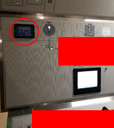
Newly Fitted Ground Fault Detection System
I was contracted to assist in debugging an issue on-board the CCGS Sir Wilfrid Laurier. As part of the vessel’s refurbishment, it was fitted with a new ground fault detection system.
During commissioning of the system, it was noted that false trips of the ground fault detection circuits were possible, caused by nearby use of VHF handheld radio transmitters.
Ground trips occurred when the detected current reached 50% threshold as indicated on the LCD.
The ground faults lead to loss of critical system functioning such as guidance and lighting circuits.
This case study was published with permission from the Canadian Coast Guard.
Initial Assessment
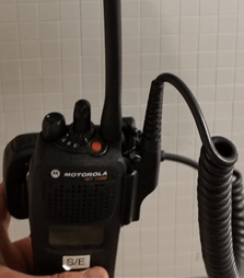
Noise Source: FM Transmitter 156 MHz – 162 MHz
The issue was repeatable and occurred intermittently when a VHF radio was used within approximately 30cm – 1 metre of the new system.
Transmitter Frequency Band
The radio transmitted in the band 156MHz – 162 MHz. Modulation was FM and channels were 25 or 50 kHz bandwidth.
Notably, the issue was most apparent when repeatedly keying the radio – i.e. pressing the transmit button repeatedly at ½ second intervals. We suspected that this coincided with the peak RF power output of the transmitter.
Fault Locations
The system was most susceptible with the radio located at the front, side and back of the instrumentation panel.
Front and side locations shown below.
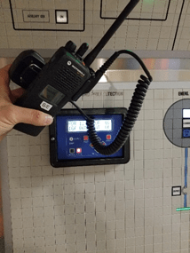
Susceptibility Observed – Front
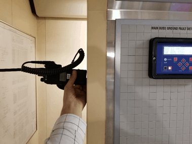
System Susceptibility Observed – RF Transmitter Positioned at Side
Test Methods
The first step in troubleshooting any EMC immunity issue is to find a method to repeatedly trigger the fault. In that way, you can begin to investigate theories and fixes whilst bench-marking the performance.
The main test method used was to use a hand-held transmitter to trigger the fault.
We attempted to isolate specific susceptible cables using the equipment shown below (signal generator, power amplifier and cable current injection probe), but we were unable to re-create the fault using that method.
This was deemed to be due to the signal generator being unable to generate the same modulation as the VHF radio (FM). It could only generate AM, which was not representative of the actual radio.
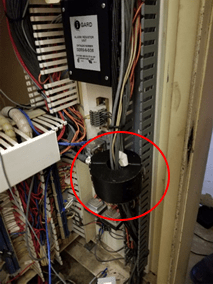
Bulk Current Injection (BCI) Probe
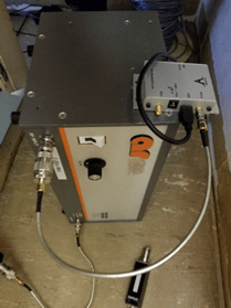
Attempt to Simulate Fault – Signal Generator & RF Amp
Radiated Immunity Fault Findings
Transmit Power v.s Test Report
Using an isotropic field probe I measured the electric field strength generated by the VHF radio. It was found to be greater than 300 Volts per metre at separations of 1-2cm! Note that because this was measured in the near-field, the actual field strength in the far-field could be much lower. It is also possible that the coupling from the radio to the field probe was predominantly capacitive when keying due to a high rate of change of voltage at the beginning of the transmission. The same would be true of the actual usage environment, i.e. the victim circuitry was within the near field of the noise source (the radio).
At separations of approximately 30-50cm, the measured field strength was in the order of 10 V/m.
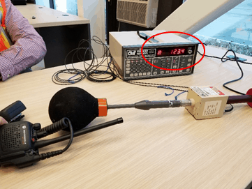
Field Strength Measurement (123 V/m shown)
This was a huge problem because the new ground fault detection system EMC test report showed that the system had been tested up to a field strength of only 10 V/m during radiated immunity field testing according to the standard IEC/EN61000-4-3.

Radiated Immunity Test Levels
The test report notes that “anomalies were observed below 110 MHz, as the EUT detected a fault condition. The fault was immediately cleared, and no relays were tripped, thus the EUT met the customer’s definition of criteria A”.
It is clear that the field strength generated by the RF transmitter in close proximity is much higher than the level used during EMC testing, so it is not surprising that this issue was not picked up during the original EMC test schedule.
Although the system passed the applicable standards at the default test levels, manufacturers are always recommended to increase test levels to match levels found in typical usage environments.
This is why it is so important for any hardware manufacturer to know what kind of electromagnetic environments their products will be used in. Otherwise faults like this can come up which can lead to unhappy customers and potentially lower sales.
Display Ribbon Cable
It was noted that the ribbon cable between the feeder modules and the display module was unshielded and had significant length.
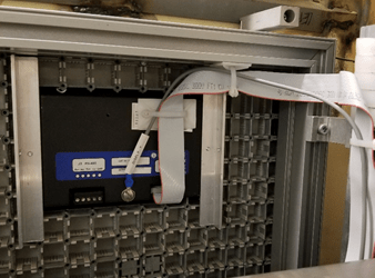
Unshielded Ribbon Cable
It was also noted that the reference/return ground for this cable was passed on a separate wire. With this kind of increased loop impedance, I expected there to be a large increase in susceptibility to radiated field coupling.
Ground/Power Rail Susceptibility
It was observed that even feeder modules without ground current sensors attached tripped in response to the VHF radio.
This indicated to us that the issue was at least in part due to noise voltages appearing on ground and/or power provided to the feeder modules.
Additionally, exploratory testing with various locations of the VHF radio showed that AC power and ground wires were particularly susceptible to noise injection.
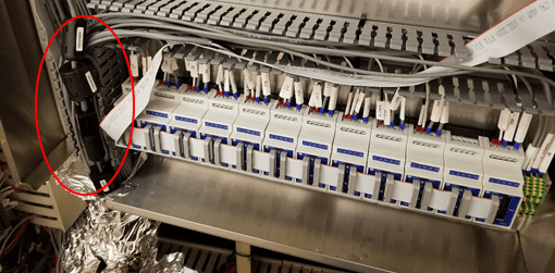
Some Modules Trip Without Sensors – CM Chokes Added to Attenuate CM Noise
Radio waves reflecting off back wall
It was observed that when someone was standing at the behind the instrumentation panel, the fault improved.
This indicated that radio waves were bouncing off the side and back walls and coupled to the exposed cable bundles at the back of the control panel.
The person at the back was absorbing some of the waves and therefore less coupling occurred to the cabling.
Unshielded Cabling
It was observed that there were many exposed cables and cable bundles at the back of the control panel. Many of these cables fed directly into the feeder module enclosure.
Significant noise currents in the order of 10’s of milliamps can be generated in unshielded cabling that is exposed to field strengths in the order of 10-300 V/m.
We fitted common mode chokes to as many cables as possible entering the enclosure. This improved the performance, but not by enough (typically chokes can yield 3-10dB improvement). It did indicate that the unshielded cable bundles were a major issue though.
As mentioned above, we noted that ground and AC power cables were particularly susceptible to noise pickup triggering faults.
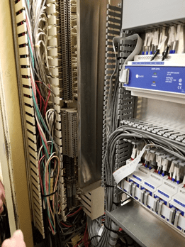
Unshielded Cables and Cable Bundles
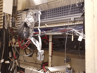
Unshielded Cables and Cable Bundles
Cable Shield Terminations
Several cables were shielded, but the shields were not terminated adequately. Many shields had ‘pigtails’ of 5-10cm in length, which at the noise frequencies involved would make the shield completely ineffective.
Additionally, many shielded cables had lengths where they were unshielded, making them much more susceptible to noise pickup.
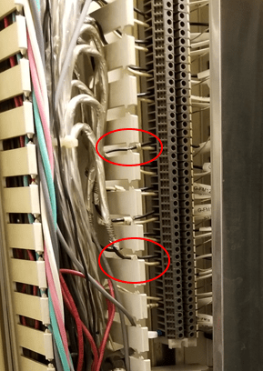
Poorly Terminated Cable Shields
Metal Enclosure
It was noted that the metal enclosure used to house the feeder modules was not sealed from an RF perspective.
The joints around the periphery were not well electrically sealed when closed and a large (20cm x 10cm) hole existed for cables to penetrate the enclosure.
Susceptible Cabling on Right Hand Side/Lower
It was noted that much or all of the cabling on the right hand side that ran the vertical length of the cabinet were unshielded. Using the radio in close proximity to this cable bundle reliably triggered the fault.
Susceptible Area at Break-out Box on Left Hand Side
Another particularly susceptible area was around the cable bundles and breakout box to the left of the metal enclosure. Again, proximity to ground and AC power wires seemed to cause the most tripping.
Recommendations/Fixes to Address Fault
As a result of the findings above, the recommendations/implementations outlined below were found to greatly improve the robustness of the new system.
Use RF Shielded Enclosure
The metal box was replaced with an RF sealed enclosure.
Initially, the original box was sealed using aluminum tape, which yielded improved performance, and then for the final installation, a custom RF shielded enclosure was fitted (shown below).
Cabling exited through a conduit rather than a hole, which greatly improve the shielding effectiveness of the enclosure.
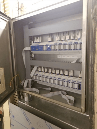
New RF Shielded Enclosure
Reduce Length of Unshielded Cabling
Due to the susceptibility of the unshielded or poorly shielded cabling/cable bundles, it was recommended to reduce the length of unshielded cabling and also to replace/move the breakout block on the left had side into a separate metal enclosure below the main enclosure.
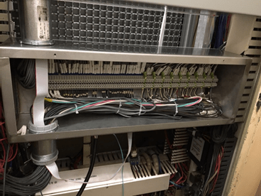
New Shielded Box and Conduit To RF Enclosure
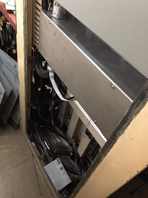
New Shielded Box Houses Breakout Block
Single-Point Enclosure Grounding
It was noted that the original system had several ground points and cables. This allowed several points of entry for noise which could then be coupled conductively to the feeder modules.
This configuration was replaced with a single point ground. The single point ground connected through a filter (more on this below) to the metal framework of the installation.
I also suspected that the whole metal instrumentation panel could be resonating when exposed to the high RF field strength. By moving to a single point ground, we could minimize the interference of the resonating chassis.
Filter Ground and AC Supply With Feed-Through Filters
To minimize noise injection on the ground reference of the feeder modules, I applied feed-through filters for the single point ground and the AC power supply cables.
These feed-through filters shunt noise to the outside of the RF enclosure so that it’s kept outside as much as possible.
These changes, along with replacing the AC power cable with a shielded twisted-pair cable significantly improved the resilience of the system to the radio.
The filter on the ground connection should connect directly to the metal framework with as short and wide (low inductance) connection as possible. Preferably <1cm and connected with large wire or copper tape.
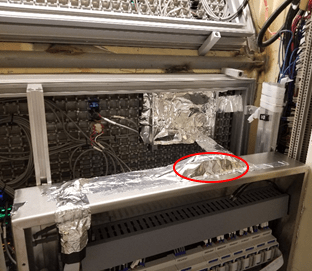
Shielded And Filtered Ribbon Cable
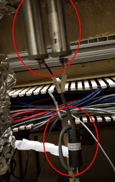
Feedthrough Filters, CM Choke And Twisted Pair On AC Power
Shield, Ground and Filter Display Flex Cable
Another modification that significantly improved performance was to shield the flex cable that connected to the display module. This modification especially improved the performance when the radio was used at the front of the control panel, to the point where the fault could no longer be triggered.
2 ferrites were added to this cable (shown below), to attenuate common mode noise and the cable was shielded using aluminum tape. The tape was electrically connected to the ground lug on the display module and to the chassis of the metal enclosure.
For future installations, it was recommended to use a shielded ribbon cable with the shield terminated to the enclosure at both ends (the ground lug at the display end).
The cable was also re-routed to enter the box at the top to minimize the exposed length.
Aluminium tape was also applied to the back of the system as shown below. The chassis of the product was plastic which otherwise offered no attenuation to the very high electric field strength.
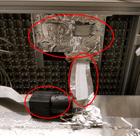
Shielded And Filtered Ribbon Cable & Back of Enclosure
Shield Back of Enclosure
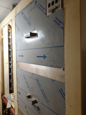
Added Shielding to Back of Cabinet
Finally, it was recommended to close up the back of the cabinet. This further shields the exposed cabling at the back.
It was noted that shielding the lower half of the cabinet was adequate to avoid almost all false triggers. This is where most of the remaining exposed cabling was located. By shielding the upper half, additional protection was added.
To maximize the shielding effectiveness of the panels, it was recommended to remove the paint at all of the joints to ensure a solid electrical connection.
It was noted that in the upper right hand corner, the panel didn’t contact the framework due to the legacy fault system. It was recommended to cut the panel to ensure a solid connection to the framework.
Final Performance
With all of the modifications mentioned above, we were no longer able to cause a false trip.
Summary
This case study showed a few very important considerations when it comes to the RF immunity of installations and systems:
- Always ensure that a system has been designed and tested to operate in an electromagnetic environment in which it’s intended to operate. In this case, the system was only designed to meet 10 V/m but it was subjected to >300 V/m fields.
- Keep cable lengths to a minimum. Do not leave loose cable hanging in an unshielded enclosure.
- Use shielded twisted pair cabling if at all possible. Ensure cable shields are terminated with as small a pigtail as physically possible.
- From a CM rejection perspective, it’s always best to use differential signalling rather than single ended.
- Use shielded cable bundle trays to route cable bundles if possible. Cable shields can be terminated inside the trays to keep shielding effectiveness high.
- If you’re using flex cables, use the shielded variety. Route the cabling flat to the conductive enclosure to minimize loop inductance and maximize rejection of common mode noise.
- Use single point grounding for a shielded enclosure. Filter this ground using a feed-through capacitor if possible.
- Use feed-through filters for the AC power inputs if possible.
- Use common mode chokes to attenuate noise coming in on signal cables.
- Shield the back of electrical panel installations to maximize RF immunity.
If you’d like to learn more about how to improve the EMC performance of your hardware products, you’re welcome to check out my Design for Compliance Emissions & Immunity Online Courses


Comments 8
Hello Andy,
a very useful hands-on problem solving exercise which indeed shows how poor installation and inadequate testing can result in field issues.
I would caution you in using a far field probe to “measure” field strengths at such close distances. These probes are calibrated in plane wave fields in either a TEM/GTEM cell or waveguide depending on frequency as you probably know and placing a monopole antenna of the radio in close proximity to the mini-dipole/schottky diode arrays/high Z wiring in the probe results in substantial capacitive coupling with uncalibrated resulting measurements.
I would agree however that the field strength is very high in the near field and that was an excellent and clearly repeatable noise source.
When testing for clients I usually double or triple the test field strengths for Radiated immunity, starting at the required level and then increasing so that my clients have a record of possible failures in unexpected environments.
Author
Thanks Braham, that’s a good point. It may be the case that the transmitter output had a very high dV/dt when keying, so the fault could be predominantly capacitive coupling related rather than radiated. I will re-write that section to mention the near-field/far-field considerations.
Very nice article. I hope you keep sharing your experiences with us. As a small company dealing with mechatronic devices, we have you and Mr. Ott’s material as main reference. Obviously, we would ask you for help when thing gets serious.
If you think I can help you with nicely finished custom RF enclosures, please do not hesitate to tell me!
Author
Thanks Alexandre.
Nice and insight full article.
Thanks Andy for sharing the practical and easy to read case study!
Good work & good report out.
It’s very good to see field resolution w/ minimal test equipment, operational / environmental broad stroke tests to identify weakest or most susceptible links, quick test w/ basic stuff to verify conclusions (aluminum tape), & reinforcing the basic best practice EMC fixes (filtering, shielding, spacing).
Seeing clip-on ferrite beads usually always means someone did a last minute patch to sneak by a test or deal with a very tight scope fix.
Canned line EMI line filters are staged / biased to maximize attenuation of LOAD sourced emissions back on to the LINE supply. For immunity situations where filtering line supply RF noise into the equipment is the goal, turn the canned EMI filter around (line into the LOAD marked filter side & equipment power to the LINE marked side). It’s a matter of who’s being filtered from who.
Typically, canned EMI filter circuits / components are directly tied to the outer “can” or enclosure of the filter, the “can” is a conductive box, & there’s typically a redundant connection point or lead wire for earth grounding the EMI filter. If the filter is mounted to an earthed surface (conductive connected mounting), the external / redundant ground wire connection becomes another ground loop & the loop can end up being a radiating antenna. This is one of the not so obvious things sometimes.
Dear Anddy sir
you have given good things about EMC product . I relay appreciate
Thanks&Regards
Shree Ram Rai