EMC TESTING: THE BEGINNER'S GUIDE
Chapter 2 - Radiated & Conducted Emissions
In this chapter of the guide, we're gonna cover the most common emissions tests. It's important to note that not all of them may apply to your product - this is just a comprehensive list of emissions tests that EMC test labs often perform on electronic products.
You can think of this chapter as the 'problem definition' chapter. We'll define the hurdles that you'll need to get over to be able to pass emissions (EMI) testing. In the later chapters, we'll address how we're going to pass these tests.
Radiated Emissions Testing
This is by far the most common EMC test undertaken around the world. There are radiated emission limits in every major market in the world and they apply regardless of product type or industry. There are a few different types of radiated emissions testing facilities that test labs use. Read on to get the low down on each of these sites.
What is Radiated Emissions (or EMI) Testing?
Radiated emissions testing involves measuring the electromagnetic field strength of the emissions that are unintentionally generated by your product. Emissions are inherent to the switching voltages and currents within any digital circuit, the only question is: how large are the emissions and do they comply with the emissions limits?
So how do EMC test labs measure radiated emissions?
Radiated Emissions Test Method
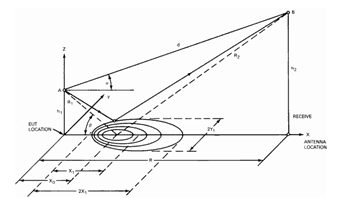 The electromagnetic waves don't extend out from your product in a nice spherical pattern.
The emissions tend to be pretty directional, so a test lab has to vary the height of the receiving antenna between 1 and 4 meters as well as rotate a turntable.
The receiving antenna picks up both the signal direct from the EUT, as well as a bounce off the ground. To increase measurement accuracy, the ground is covered with an electromagnetically reflective surface (aluminum, steel, wire mesh etc..) and this ground plane must be relatively flat.
The test lab will scan the frequency band of interest and look for emissions that are close to the limits. Using a process called 'maximization' (described below), the test lab focuses in on each of these emissions, and quantifies the amplitude of the field strength.
Class A digital device:
A digital device that is marketed for use in a commercial, industrial or business environment, exclusive of a device which is marketed for use by the general public or is intended to be used in the home.
Class B digital device:
A digital device that is marketed for use in a residential environment notwithstanding use in commercial, business and industrial environments. Examples of such devices include, but are not limited to, personal computers, calculators, and similar electronic devices that are marketed for use by the general public.
Types of Radiated Emissions Test Sites
There are two primary types of test sites that are used for measuring radiated emissions from electronic products. The goal of these test sites is to accurately measure the emissions that come from your product and ensure that they comply with the relevant limits.
The are over 1000 FCC listed/accredited EMC test sites around the world, each of which contains at least one of the test sites described below. And that number doesn't include any EMC test sites that are not registered with the FCC.
Read on below for a description of the test sites so that you know what to expect....
Open Area Test Site (OATS)
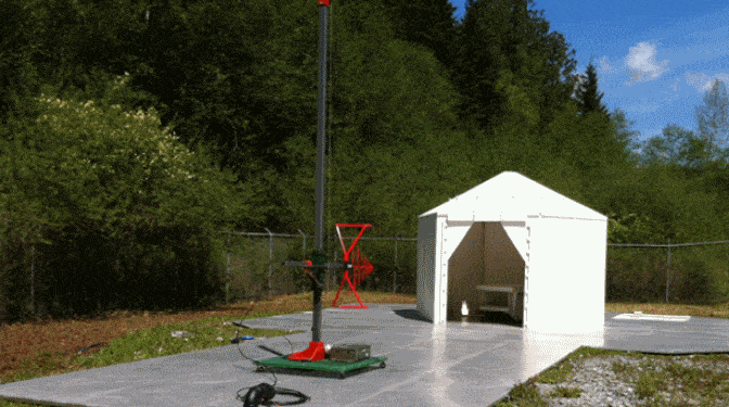
An "OATS" or an open area test site is the most common radiated emissions test site.
They are most commonly constructed to comply with the requirements of ANSI C63.4 (for North America and elsewhere) and CISPR 16-1-x (for Europe and elsewhere).
The distance between the antenna and the equipment under test (EUT) is typically 3m, 10m or 30m. The measurement distance is important because you want to ensure that you are measuring the field strength in the far field as opposed to near field.
At 30 MHz, the wavelength is 10m. As you approach the near field or fresnel region (region between near and far field), the electric field may not yet be stable and the measurements will be less accurate.
Some standards mandate a specific separation, while others allow the use of 2 or more different separations. Because the strength of the electromagnetic field varies with distance, the limits are re-calculated at each measurement separation.
Although it is usually acceptable for test measurements to be compared between different measurement distances by factoring in an extrapolation factor of approximately 20dB/decade, in reality there are issuesthat make comparisons of measurements at different types of facilities problematic.
Semi Anechoic Chamber
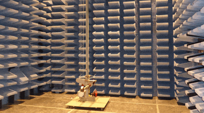
A semi-anechoic chamber (or SAC for short), is just like an OATS, only it's housed within a shielded (metal) room.
This is really helpful because it attenuates the background (ambient) radio signals, so it's much easier to distinguish what's coming from your product vs. the background signals.
The inside of a SAC is lined with RF absorber material so that reflected signals are kept to a minimum.
Without these absorbers, the measurement antenna would receive an unquantifiable signal contribution from wall and ceiling reflections, making the measurements quite inaccurate.
Chambers are quite expensive (>$100k), but they are a good solution to measuring EMI in a noisy environment.
Related Post: The Anechoic Chamber Guide For Emissions, Immunity and RF (Wireless) Testing
Spectrum Analyzer
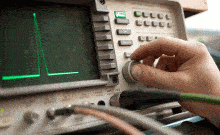
A spectrum analyzer (or alternatively an EMI receiver) is the backbone of an EMC test lab's emissions measurement equipment. Their specifications and costs vary wildly. If you're looking to invest in a spectrum analyzer for compliance testing, here are a few qualities that you want to look for:
- Low noise floor
- Wide frequency range (ideally it covers down to the lower end of conducted emissions up to the upper end of radiated emissions)
- Peak, AVG and QP detectors
- Common EMI bandwidths: 9kHz, 10kHz, 100kHz, 120kHz, 1MHz
- GPIB or other computer interface port
- Software for adding/subtracting transducers + applying limit lines
Maximization
Maximization is the procedure that test labs use to find the maximum amplitude of the emissions from your product. Once they find several candidates for the highest emissions, they will perform a maximization procedure like this:
1. Manipulate cabling to product highest amplitude signal
2. Rotate the EUT 360 degrees using an automated turntable to find the maximum amplitude of signal
3. Move antenna up and down to find the maximum amplitude of signal. If it's higher than previously seen, go back to step two
4. Flip polarazation of antenna (horizontal to vertical or vice versa) and repeat steps above
5. Vary equipment modes of operation to check for variations during testing. Find worst case mode
NSA
NSA doesn't stand for anything as interesting as the National Security Agency. In the world of EMC, NSA is short for 'Normalized Site Attenuation'.
NSA surveys are used to verify the performance of a radiated emissions test site. The EUT is replaced with a transmitting antenna and a receiving antenna picks up the signal.
By comparing the received signal to a theoretically ideal value, test labs ensure that their measurements are within +/- 4dB of an 'ideal' site.
What Are The Emission Limits And Frequency Ranges?
The limits for radiated emissions vary by geographical region and by product type. Europe and North America's limits are very similar, although Europe's limits are slightly stricter in certain frequency bands.
If your product has an industry specific standard such as military, automotive or aerospace, the limits are usually much stricter and harder to pass.
Radiated Emission Limits
Below you can see a sample radiated emissions plot from an EMC test lab. The green line is the limit line for Europe and the blue line is for the FCC.
You can see that they're very similar, but there are subtle differences. It's possible to pass FCC but fail CE emissions limits, but not vice versa!
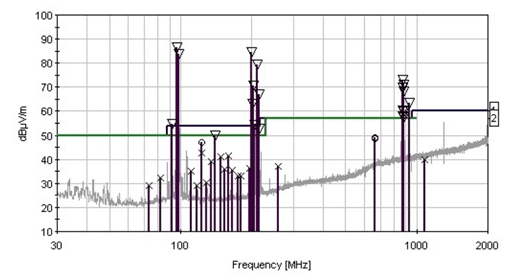
You can tell that this plot is from an OATS because you can see several large ambient signals in the FM and cell phone bands.
What Frequency Range is Measured?
The frequency range that a test lab needs to investigate usually varies with the highest speed clock rate present in the device. For some industry and product specific standards, the frequency range is fixed, but for the FCC you can see how the upper frequency range of measurement relates to the highest clock frequency in your design.
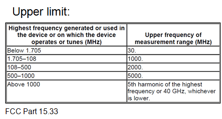
The lower frequency range is defined by the lowest frequency clock used in your design. For example, if you're using a 16 kHz crystal for timing, the lab should measure down to that frequency.
Measuring frequencies below 30 MHz usually necessitates the use of a loop antenna which picks up magnetic fields. Magnetic fields tend to be dominant at lower frequencies.
Measurement Transducers
With radiated emissions testing, everything that interacts with the RF signal has some effect on that signal.
Just as a resistor will drop a voltage across it if current flows at DC; a cable, attenuator, connector or adapter will similarly cause the amplitude of an RF signal to drop. Equally as important is the fact that the amount of attenuation varies with the frequency of the RF signal.
The gain of antennas and amplifiers also vary with the frequency of an RF signal.
For an EMC test lab to get repeatable, accurate results, it's crucial to have calibrations of all transducers used in the measurements. The transducers include:
- RF cables
- Attenuators
- Antennas
- RF amplifiers
- Connector adapters
Measurement Antennas
To cover the entire frequency range of interest, test labs often need to use several different antennas.
This is because different antennas have different gain profiles across different frequency ranges. Ideally you want a high, flat gain response across your measurement band of interest. Without a reasonable amount of gain, the measured signal fed into a spectrum analyzer or EMI receiver could be too small and fall below the noise floor of the measurement instrument.
For high frequency measurements (> 1 GHz), an RF amplifier is sometimes required to boost the signal.
Check out the most common types below.
Loop
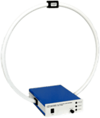
Freq: 10kHz-30MHz
Biconical
Freq: 30MHz ~ 300MHz
Log Periodic
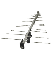
Freq: 300 MHz ~ 1 GHz
Horn
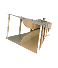
Freq: 1 GHz ~ 26 GHz
How Hard is it to Pass?
This is the $64,000 dollar question and the answer really depends on what your product is, how it's been designed and how strict the limits are. I've seen radiated emissions failures from products as simple as a 25 MHz, single microprocessor unit (mostly due to the 2 layer construction which made return paths very segmented), and I've seen multi-gigahertz computers sail through emissions testing on the first pass.
Passing EMC testing first time around comes down to good understanding of the problem, proper preparation and the skill of the design engineers.
The chapter on "EMC testing preparation" in this guide will give you a full breakdown of the process large multinational companies use to consistently pass EMC testing.

What Are The Typical Failure Modes?
There are a virtually unlimited number of ways that you can fail a radiated emissions test. Here is a small sample of the classic design issues:
- Noise on the cabling
- Poor board grounding
- Non-optimized layer stack
- Ineffective board decoupling
- Poor cable termination
- Non-compliant auxiliary equipment
- High PDN impedance
- Poor signal integrity
- Choosing wrong class of power supply
- Poor component placement
- Cuts in return paths
- Large current loops
- Lack of grounding for crystals, heat-sinks and LCDs
- Stubs
- Segmented ground fills
- Critical nets change reference planes
- Signals close to edge of reference plane
- Poor decoupling capacitor placement
- Poor decoupling capacitor routing
Conducted Emissions Testing
What is Conducted Emissions Testing?
Your device creates electromagnetic energy and a certain portion of it will be conducted onto the power supply cord.
In order to restrict the amount of interference your device can couple back onto a power supply, test labs measure these emissions (usually from 150 kHz - 30 MHz, and verify that they comply with specified limits.
This helps to ensure that the local power supply remains relatively 'clean' and nearby devices won't be affected by your device.
Conducted Emissions Test Setup
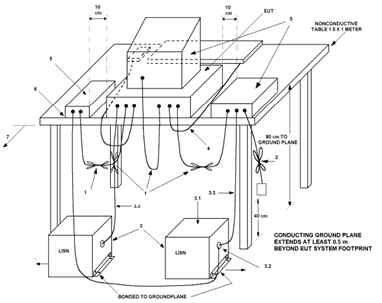
Above, you can see a diagram of a typical conducted emissions test setup, according to ANSI C63.4. The LISN (or LISNs) sit on the ground, while your product sits on a table (or remains floor standing if the equipment is large).
The RF port of a LISN connects directly to a spectrum analyzer (or via a transient limiter to prevent damage from voltage spikes).
Conducted Emissions Applicability
Conducted emissions testing is usually performed on devices that connect to an AC power supply. That is regardless of whether you're using a pre-certified AC-DC power supply adapter.
For some standards, there area also limits placed on devices that operate from a DC power supply.
What Are The Frequency Ranges and Limits?
Frequency Range
A very common frequency range called out by conducted emissions standards is 150 kHz to 30 MHz. But that range may be higher or lower for specific standards.
Different standards call for different frequency ranges and different impedances, so LISN manufacturers usually carry a line of products to satisfy all of these requirements.
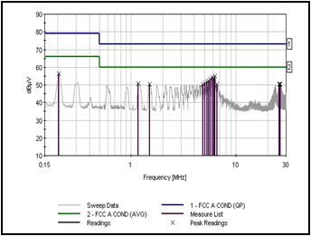
Conducted Emission Limits
Below you can see the FCC's conducted emission limits for class A and class B devices. You'll notice that class B limits (for domestic environments) are more strict, probably because the number of devices expected in a household is large, and users want to be sure that devices won't interfere with each other through conducted noise on the AC power supply.

What Are The Risks of Conducted Emissions Testing?
It's really common for devices to fail conducted emissions testing. Even if your equipment uses a pre-certified external AC-DC power adapter, that doesn't guarantee a pass. There are a couple of reasons for this:
- The power supply may be non-compliant.
It is not uncommon to see power supplies that are supposedly compliant, but when re-tested, they are actually non-compliant. That could be due to a number of reasons including batch to batch variations, flaws with the original testing or hardware changes since the original testing.
- The original power adapter was tested using a DC load
Typically, OEMs who have their power supply adapters tested, do so with a DC load attached to the output, with the value selected to correspond to the highest rated current draw. Your equipment will pull both a DC and AC/RF current, so the emissions profile of the adapter will be different than when originally tested.
LISN
A LISN is a low-pass filter typically placed between an ac or dc power source and the EUT (Equipment Under Test) to create a known impedance and to provide an RF noise measurement port which connects to a spectrum analyzer or oscilloscope.
You need a known impedance because otherwise the measurements won’t be repeatable. The impedance of AC power supplies vary from outlet to outlet, so a LISN standardizes this impedance between labs.
A LISN also filters and isolates unwanted RF signals from the power supply source. This is helpful for the case when the power supply of the test lab is noisy - the filtering in the LISN minimizes this noise and (ideally) allows the lab to measure only the noise due to the EUT.
What's in a LISN?
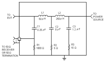
The circuit inside a LISN is relatively simple. It just consists of some filtering, a power supply input and output, and a port that connects to a spectrum analyzer.
For AC LISNs, there are often 2 identical circuits inside so that you can measure the noise on the line and neutral signals without needing a separate LISN.
There are many types of LISN to satisfy the specifications of different standards. Here are some of the properties that vary:
- Maximum current/phase
- Impedance presented to EUT
- No. of phases
- AC or DC
- Frequency range
Conducted Emissions Recommendations
Without going into huge detail on circuit design for conducted emissions compliance, there are a few simple ways that you can minimize the risk of failing conducted emissions testing:
- Always source a power supply that is rated for the limits that you need to pass
If your device is a 'class B' device, then make sure to source a class B adapter. An adapter that has only passed class A limits, is unlikely to result in a pass for you. A class B adapter doesn't guarantee a class B conducted emissions pass, but it will certainly help.
Similarly for stricter military, medical, automotive or aerospace limits, always source a supply who's specification claims compliance with the relevant limit.
- Bring at least 3 different power supplies to the test lab
If your device uses an external AC-DC power adapter, bring equivalents from different manufacturers just in case. If you fail, you can swap it out and see if the other supplies result in a pass.
- Check your power supply rails for ripple
If you have nice clean power supplies, the chances are that your PDN and decoupling are in good shape. If you see excessive ripple or spikes from switching power supplies, this noise may well be present at the AC side of your power supply.
Ethernet Conducted Emissions
Did you know that in some geographical regions (e.g. Europe), testing of the noise on Ethernet ports is also usually required?
Your device can inject noise back onto an Ethernet network and in some standards, there is a limit to the amplitude of that noise.
Flicker & Harmonics Testing
What is Flicker & Harmonics Testing?
Flicker and harmonics testing are another form of emissions testing. These EMC tests are usually performed to the EN61000-3-2 and EN61000-3-3 standards respectively.
In Europe, these are considered to be 'horizontal' standards, which means that they apply to almost all types of electronic or electrical equipment that enter the EU.
There are many caveats to this, but you can use our EMC testing standards finder tool to see if these standards might apply to you!
Harmonic Current Testing (61000-3-2)
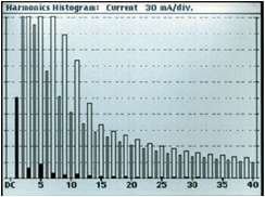 This test is designed to measure the harmonic current requirements of an EUT.
It's usually associated with switch mode power converters and other non-linear loads such as motors, transformers and lamp dimmers/ballasts.
By limiting the harmonic current draw requirements, the harmonic load on local power supplies is reduced, which helps to avoid overheating and increases efficiency. It's an important piece of the puzzle for power companies to maintain the quality of AC distribution systems.
Voltage Flicker Testing (61000-3-3)
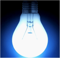 One of the first EMC tests ever - with limits specified back in the 1890s in London, England. Degrading electric lamps would cause arcing between contacts which in turn would cause nearby lamps sharing the same power supply to 'flicker'.
The impedance of the power supply cabling was much higher than it is today. The non-linear current draw of an arcing lamp induced voltage variations on the power supply, thus affecting nearby lamps.
The flicker limits today actually still relate back to the amount of visually perceivable flickering on an incandescent light bulb.
Flicker & Harmonics Test Equipment
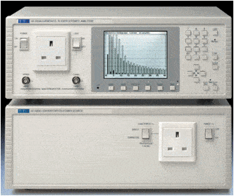
There are some fairly low cost test equipment solutions for measuring flicker and harmonics current.
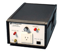
This one shown to the right is from TTI and it covers both flicker and harmonic current test requirements. Rated up to 16 A @ 230V, it suits a wide range of relatively low power products.
The bottom section of the equipment is a very clean power supply and it presents a known impedance to the analyzer (the top section).
Read on below to see what the analyzer is actually doing...
Inrush Current Limits
The voltage variation limit in EN61000-3-3 effectively creates an inrush current limit for devices when you first switch them on.
The maximum inrush current limit varies depending on the voltage variation limit (dmax) selected for your equipment, but it can be in the range 20A-30A averaged over the first 10ms of on time.
The inrush current at power on is measured by turning the power on and off to your product 24 times. The highest and lowest recorded values are thrown away and the middle 22 are averaged to get the final inrush current value which is then compared with the limit.
Class Definitions
The limits for the harmonic current testing depends on the class of the EUT. Here are the class definitions:
A: Balanced three-phase equipment, and all other equipment except that stated in one of the remaining three classes
B: Portable electrical tools, which are hand held during normal operation and used for a short time (a few minutes) only
C: Lighting equipment, including dimming devices
D: Equipment having an input current with a “special wave shape” e.g. Personal computers and personal computer monitors, Television receivers. Note: Equipment must have power level 75W up to and not exceeding 600W
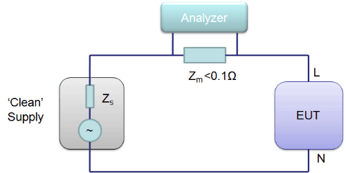
Flicker Measurement Circuit
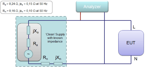
As you can see, the simplified diagram of this measurement circuit isn't very complex.
All the analyzer is doing is measuring the voltage across the EUT. There is a calibrated complex source impedance, so the analyzer can work out the voltage fluctuations across a range of frequencies.
Harmonic Current Measurement Circuit
Magnetic Field Testing
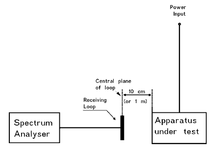
Magnetic field testing is a pretty uncommon test, but some standards do mandate it. Magnetic fields are predominantly present at lower frequencies and measurements are usually made with a large loop antenna that is placed very close to the EUT.
You can see a sample test setup specified below, which is taken from the professional audio product family standard (EN55103).
We're also going to take a look at magnetic field immunity testing in the next chapter.
Conclusions
If you've read this far, you now have a great idea of every single emissions test that your product may have to comply with!
Now you know the 'problem definition', i.e. this is the hurdle you have to jump over. In the following chapters, we'll begin to dig into the 'problem-solutions' so that you can increase your chances of passing these tests.


Comments 22
Hello Andy,
The beginner’s guide to EMC (free training) is part of the EMC essential training?
Thanks.
Author
Hi Jacky, the beginner’s guide is a summary of a portion of the EMC Essentials video training. There’s more material and I go into much more detail in the training program. If you want the most comprehensive training with lots of tips then the EMC Essentials course is the way to go. Otherwise, this beginner’s guide is a good start.
You green box above for “Inrush current” is a copy of the “Ethernet conducted emissions” from the green box above it.
Sorry to be nit picky, you’re doing a great job here.
Author
Thanks Tim, I’ll get that sorted out shortly.
Hello Andy,
For the EMC essential video training does it come with a text book or something? And the green box idea is cool I quite like it.
Thanks a lot.
Author
Hi Jacky, thanks for the question. Sent you an email reply.
The tip on the cheap standards would have saved me $1,000 last year. It will save me $1,000 this year. Some of those standards are ridiculously priced in most of the EU countries. Great resource. Who would have thought to go to Estonia.
Author
Yeah, it’s crazy.
Hi andy :
Why product (like AC FAN) failed by different type Lisn?
Lisn model : NSLK 8127 and NNLK 8130
thanks
according to ISO 17025 requirment uncertainty measurement
how to implemented it in conducted emission testing.
thank you very much
I’m a Theremin developer and I’m curious as to how this device might be perceived by the EMC community. Voltage swing on the “antennas” (capacitance sensors) of a good Theremin can be several hundred volts p-p from 250kHz to 2MHz (depending on the design) with 5% frequency variation over the hand playing field. The voltage is generally sinusoidal. The “antennas” are quite a bit smaller than the wavelength at these frequencies, so the RF radiation isn’t efficient by any means, though I’m sure there is RF being radiated. Any thoughts on this? If it seems immediately problematic, I’m wondering how Moog Inc. gets away with manufacturing and selling things like the Etherwave on the open market?
Author
Hi Eric, interesting issue. Without digging into it in depth, you’re likely right that it would exceed the Part 15 unintentional limits significantly. For FCC authorization, I’d look at Part 18 rather than Part 15 to see if it could qualify as an ISM device. These are allowed to emit much higher levels within specific bands. Things like arc welders and ultrasonic devices can fit into this. One of the criteria is that the energy is used to ‘do work’ rather than to communicate like a wireless transmitter. Check the Part 18 scope to see if it can squeeze in.
Eric,
Regarding radiated emissions, I’m designing some hardware for the lighting industry that may unintentionally radiate a CW sinusoidal waveform in the 100Hz to 200Hz frequency range. Would this fall under any of the EMC standards or is to low a frequency? Is there any kind of low frequency cutoff for the standards?
Thanks!
Hi sir
1) If I want to check radiated emission in our factory ,Is there any instrument to check radiated emission.
2) how to control radiated emission.
3) which component generate radiated emission.
I have one question that is , in CISPR 15 limits are given for loop diameter of 2 m,3 m and 4 m only. then if i have loop diameter other than 2m,3m and 4m then how i can calculate limits for other loop diameter.
Is there any separate test as Magnetic Field Testing in EMI, Or Is it same as Magnetic field Immunity testing in EMC?
Hi Andy,
I’m study about EMC testing for motorcycle.
I’d like to know purpose of antenas.
They simulate frequency of surrounding electronic/ electric device, don’t they?
Hello Andy,
I am very curious about DC-DC power supply emc standards.
Is there any regulations in europa about DC-DC power supply?
Thanks.
Are there any tests or devices that measure electromagnetic fields for the purposes of circuit board fault-detection—-(good board/bad board patterns)?
Author
EM fields emanating from a circuit board would be a fairly poor proxy for circuit board fault detection I’d imagine. Far better to use regular old test probes on the board to measure voltages and currents.
If you were determined to do it using EM field measurements, there would need to be a measurable difference in the scans for a working vs non-working board that. The difference would need to be greater than any possible measurement tolerance. Any transducers would suffice including near field probes, current probes, antennas, TEM cells or NF scanners.
Manufacturers often spot check RF transceiver performance on a production line, but checking EM signatures for standard output is rare. I’ve seen a couple of manufacturers use TEM cells or EMSCAN units to do it, but it’s a luxury.
I am completely new to the EMC field, so please forgive me if I say something wrong. I had a small question regarding radiated emissions’ test.
Would an empty measurement have an effect on the main measurement with the DUT? I mean would the emission from the DUT are modulated on to the empty measurement?
For Example, in norm 12895:2015 the limit lines are 34dBuV for the initial frequency range (30MHz till 75MHz). I have noticed few empty measurements of few EMC laboratory which already start around 20-23dBuV. So if the measurement with DUT are modulated on the empty measurement, then we have just around 10dBuV left for the DUT to emit.
I got this doubt during our last EMC test. The empty measurement of the EMC chamber was already around 20-23dBuV and after we tested our product in the chamber we were almost around 32-33dBuV (thank god we didn’t cross the limit line). At that moment my doubt was if it is our component that has so much of emission or the chamber itself isn’t well insulated?
An insight on this would be very helpful.
Hi Andy ,
May I ask the reasoning behind why there are different emission /immunity limits for different frequency ranges ?
Is it possible to claim that higher the amplitude of a particular frequency, the higher the risk of EMI ? If so why ?
Thank you in advance