
EMC TESTING: THE BEGINNER'S GUIDE
Chapter 5 - Pre-Compliance - EMI
In this section of the guide, we're going to dig into an important part of preparing for EMI/EMC testing: emissions (EMI) pre-compliance testing and equipment.
You'll learn about various options for test equipment, what an ideal test site looks like and what you'll want to avoid with test equipment purchases.

EMC Pre-Compliance vs. EMC Troubleshooting Equipment
Let's keep in mind that the main goal of emissions pre-compliance testing is to work out whether your device is going to pass or fail at an EMC lab. It isn't whether your device is emitting radiation - in fact we know it definitely is - we just want to know whether those emissions are within the limits.
Some EMC test equipment claims to be 'pre-compliance' equipment when it's actually only useful for EMC troubleshooting. As an example, a near field probe is good for tracking down an emission source and isolating the frequency of the emission, but it's next to useless for telling you whether that emission will be a problem at an EMC test lab.
EMC test labs go to great lengths to create a test site that provides accurate field strength measurements. Despite their investment of tens or hundreds of thousands of dollars in test equipment and facilities, they can still only barely meet the acceptable error budget, which is +/- 4dB from an 'ideal' test site.
Often FCC registered test sites struggle to even meet this error budget as outlined in this 'elephants in the test room' webinar.
You typically won't be able to get anywhere near +/- 4 dB of an ideal measurement using troubleshooting EMC equipment. The error may be closer to +/- 40 dB which is no good for working out whether you're going to pass or fail at an EMC test lab.
So when we're choosing emissions pre-compliance test equipment and making emissions measurements, we need to keep this error budget in mind. If we can be within +/- 4 dB of an ideal site, then we're doing as well as a full compliance EMC test lab. To do that, you're going to need a full compliance setup, which we'll get into below.
Without investing in a full compliance setup, a more modest goal might be to get within +/- 10dB of an ideal site.
If we factor in a margin of 10 dB with our pre-compliance measurements, we could get a very good idea of whether we'll pass or fail at a test lab.

EMC Troubleshooting
EMC troubleshooting equipment like near field probes are good for isolating RF sources and frequencies. You can make reasonable 'relative' measurements, but not so good 'absolute' measurements.
EMC Pre-Compliance Equipment
Good EMC pre-compliance equipment is able to either measure directly or extrapolate to 'absolute' field strength values in the far field (at 3m or 10m measurement distances typically).
Near Field vs Far Field Measurements
 With near field probes, you're typically measuring an electric or magnetic field in the near field (within 1 wavelength) as opposed to the far field.
When you're measuring in the near field, it's almost impossible to accurately extrapolate to an absolute field strength value in the far field because the relationship between the E (electric) and H (magnetic) fields are complex.
In the near field, there are strong inductive and capacitive effects from the PCB/system structures that are behaving like antennas, which causes the fields to behave unlike far field radiation fields.
Antenna Separation
At an FCC listed/accredited measurement facility, the separation between the equipment under test (EUT) and the measurement antenna is typically a minimum of 3 meters, but preferably 10 meters.
Measuring at 10 meters means that you're measuring at least 1 wavelength away (some people's rule of thumb definition of the beginning of the far field region) at a frequency of 30 MHz which is often the lower end of the measurement range. This means that for the most part, they're measuring the electric field strength of a stable wave in the far field.
Absolute vs. Relative Measurements
Making relative measurements with equipment like near field probes can be useful for EMC troubleshooting, but it doesn't give us a decent idea of whether our product will pass at a lab.
Full compliance EMC test labs can spend hundreds of thousands of dollars on EMC test equipment to be able to get accurate and repeatable measurements as well as create accurate and repeatable immunity test levels.
At a full compliance facility the measurements are absolute field strength values measured at a particular separation between the EUT and antenna.
What Makes a Full Emissions Compliance Test Site Accurate?
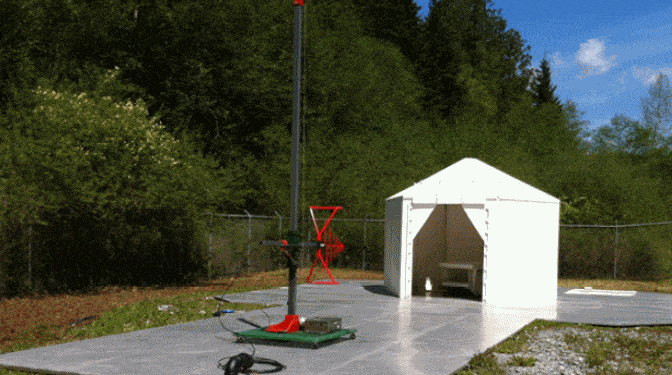
QAI 10m OATS Vancouver
If we want to make accurate pre-compliance emissions measurements, we need to know what an ideal test site looks like and what the characteristics are that we ideally want to copy.
Here is an outline of the main equipment and facilities of a full compliance lab that help them to meet the +/- 4 dB error budget.
EMI Test Site/Area
The way in which an emissions test site is constructed has a huge bearing on the potential accuracy of the measurements. Below I'll go into the important factors of designing an accurate test site.
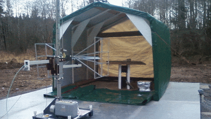
Open Area Test Site (OATS)
The properties of an open area test site that allow it to meet the +/- 4dB error budget are:
- Minimal RF reflective objects close to the measurement area
It's important to keep a large clearance between test area and RF reflective (metallic) objects to ensure that the contribution of reflections received by the antenna are negligible.
- Large and flat RF reflective ground plane
The measurement antenna actually receives a field directly from the EUT plus a reflection off the ground plane. It's important that this ground plane is flat so that the reflection is predictable and we can account for it when making measurements.
- At least 3m separation between the EUT and the measurement antenna
As mentioned above, it's important to be in the far field, or close to it, to make accurate repeatable measurements. At 30 MHz, one wavelength is 10m and at 100 MHz one wavelength is 3m. At closer measurement distances, you enter the near field and measurements get much less accurate.
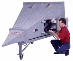
Semi-Anechoic Chamber (SAC)
When you're using a semi-anechoic chamber, there are a few important factors to consider.
A chamber essentially a sealed metal room with RF absorbers lining the inside.
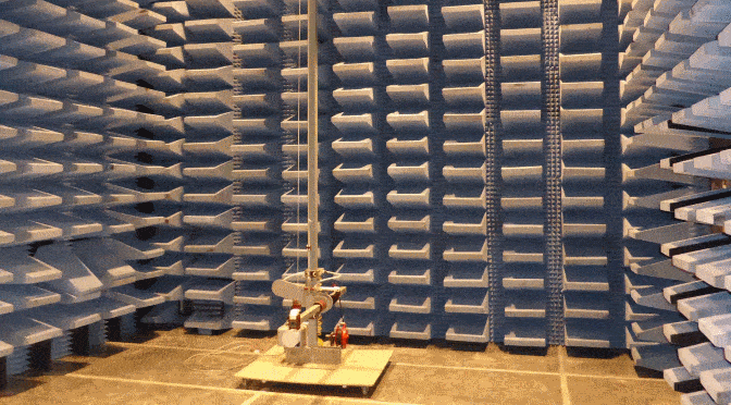
QAI 3m Semi-Anechoic Chamber Vancouver
The dimensions of the chamber itself can affect the measurement and the dimensions are influenced by the standards that you want to comply with. You would want to look for the size of chamber called out in the standard that applies most commonly to your product.
Here are some more variables of semi anechoic chambers that influence measurement accuracy:
- The type of absorber material (this needs to be selected carefully to make sure you get adequate attenuation across a wide frequency band, otherwise you could get reflections or standing waves.
- Antenna separation - generally 3m, 5m or 10m but smaller chambers exist. Due to the near field effects and limited absorber performance, chambers smaller than 3m would struggle to meet +/- 4dB measurement accuracy across 30 MHz - 2 GHz. If you're just testing high frequency transmitters, the wavelength is much smaller and you can still be measuring in the far field at closer separations.
This comprehensive guide to anechoic chambers from ETS Lindgren goes into much more detail on this subject.
Full Compliance Test Equipment
As well as a well designed measurement area, to meet the +/- 4 dB error budget EMC test labs also have to invest in accurate measurement devices and transducers.
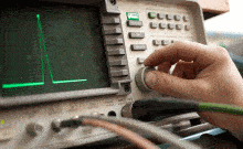
Spectrum Analyzer/EMI Receiver
Every test lab needs either a spectrum analyzer or EMI receiver to make accurate RF measurements. The performance of these can vary over time and it's important that they're properly calibrated using a high accuracy source periodically. As well as covering the entire frequency range that you need to investigate for your product (e.g. 30 MHz - 5 GHz), the spectrum analyzer also needs to have the correct 'detectors' which match those specified in the standards. Standards typically dictate 'peak', 'average' and 'quasi-peak' detectors. While most spectrum analyzers are able to perform 'peak' and 'average' measurements, a 'quasi-peak' detector is usually an optional extra. Resolution bandwidths (RBW) are another important factor of spectrum analyzers/EMI receivers. Standard EMI bandwidths are 9 kHz, 10 kHz, 100 kHz, 120 kHz and 1 MHz. These bandwidths are defined in the standards that apply to your product.
If your spectrum analyzer doesn't have all of the bandwidth options that are called out in the applicable standards, this is likely going to add a few dB to your error budget.
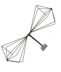
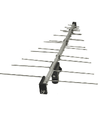
Antenna(s)
Of course the measurement antenna plays a key role in measurement accuracy. The gain of antennas varies with frequency, so you need to know what the gain is at many points across the spectrum of interest. Antennas must be individually calibrated to get the exact antenna factors needed to extrapolate from the raw measurement values to an accurate field strength measurement. Otherwise the raw data you see on your spectrum analyzer is virtually meaningless.
Turntable
Every FCC OATS or SAC has a turntable. This is required because the emissions from the EUT are usually directional. That is, the emissions don't usually extend in a nice uniform sphere from the EUT - there tends to be an orientation of EUT that produces the highest field strength. The turntable revolves the EUT 360 degrees to present every angle of the EUT to the measurement antenna. When you rotate the EUT you can often see variations in the measurement of +/- 20 dB. If your pre-compliance test setup doesn't revolve the EUT, then your error budget will be vastly increased.
Antenna Mast
In the same way, the maximum field strength at the antenna will be at some particular height. A full compliance test lab needs to move the antenna up and down a 4 or 6 meter antenna mast to make sure it has found the point where the field strength is at a maximum. Again, moving the antenna up and down can easily see measurement difference of several 10's of dBs. If your pre-compliance test setup does not have a movable antenna mast, that's also going to increase your error budget significantly.
Cable
The cable from the measurement antenna to the spectrum analyzer/receiver is also a 'transducer'. The attenuation of the cable varies with frequency and can easily attenuate your signal by several dB at higher frequencies. It's important to calibrate your cables so that you know how much signal is being lost at every point across the band of interest. For your pre-compliance setup, I'd recommend buying a cable that comes with calibration data, or calibrating it yourself with a network analyzer (or signal generator + spectrum analyzer).
What's Your Budget?
 The options available really depend on your budget. If you only want to spend $1k then you're going to have 'significant challenges' recreating the measurements that an accredited EMC testing lab will make.
I'm going to outline some purchases you can make at 3 price points below: $1k, $10k-$15k and $100k.

$1k Budget
With a $1k budget, you're going to have a hard time getting accurate RF pre-compliance measurements. On this budget, the measurement error (or more specifically, the error associated with an extrapolation to a far field absolute field strength measurement) will probably be so large that the measurements will typically just be useful for EMC troubleshooting or getting an extremely loose idea of what the emissions sources and frequencies are.
You won't be able to (at least to my knowledge) be able to get anywhere near +/- 10 dB of an idealized far field measurement across the frequency range 30 MHz - 2 GHz.
With that said, here is the equipment I would buy on a $1k budget:
Spectrum Analyzer ($150-$800)
On this budget you're going to have to get creative when you're purchasing a measurement instrument.
Follow my methods in the "How to Find Test Equipment Bargains" guide and pick up a cheap spectrum analyzer such as a 'pocket RF explorer' or perhaps a USB spectrum analyzer dongle.
These won't have great performance, sensitivity or amplitude accuracy and will probably lack some of the RBW settings required for EMI testing. But they will at least give you the ability to measure radiated fields with a degree of accuracy.
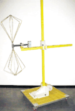
Near Field Probes ($10-$350)
Couple your USB spectrum analyzer with a cheap or homemade set of near field probes and you'll have a decent EMC troubleshooting kit. As I mentioned before though, measuring in the near field won't give you a great extrapolation to a far field measurement that you're really looking for.
These are available for sale in our online store.
For slightly more accurate far field measurements, you'll want to get an antenna instead.
Cheap Antenna ($10 - $700)
Getting an antenna that will give you usable RF measurements on this budget is tricky but possible.
The first thing to do is identify the frequency range of interest. For most unintentional radiators, that would be 30 MHz - X GHz where X is anywhere between 1 GHz and 40 GHz (in the case of the FCC). 30 MHz - 2 GHz will cover the majority of issues for unintentional radiators with internal clock frequencies <500 MHz.
You can buy cheap off the shelf antennas covering the UHF and VHF bands (check ebay) for $10 - $150. The key is to find antennas that cover the whole band you want to investigate AND come with some sort of calibration or gain data.
To get measurement data that's useful for comparing with a test lab, you need to know the gain of the antennas. Otherwise again, you're just going to have an EMC troubleshooting setup.
If you're diligent and a bit lucky, you'll be able to pick up a used measurement antenna on ebay for a few hundred dollars. Look for bi-conical antennas for the 30 MHz - 200 MHz range and log-period antennas for the 200 MHz - 2 GHz range.
Above 1 or 2 GHz, you'll need a horn antenna which can start getting pricey.

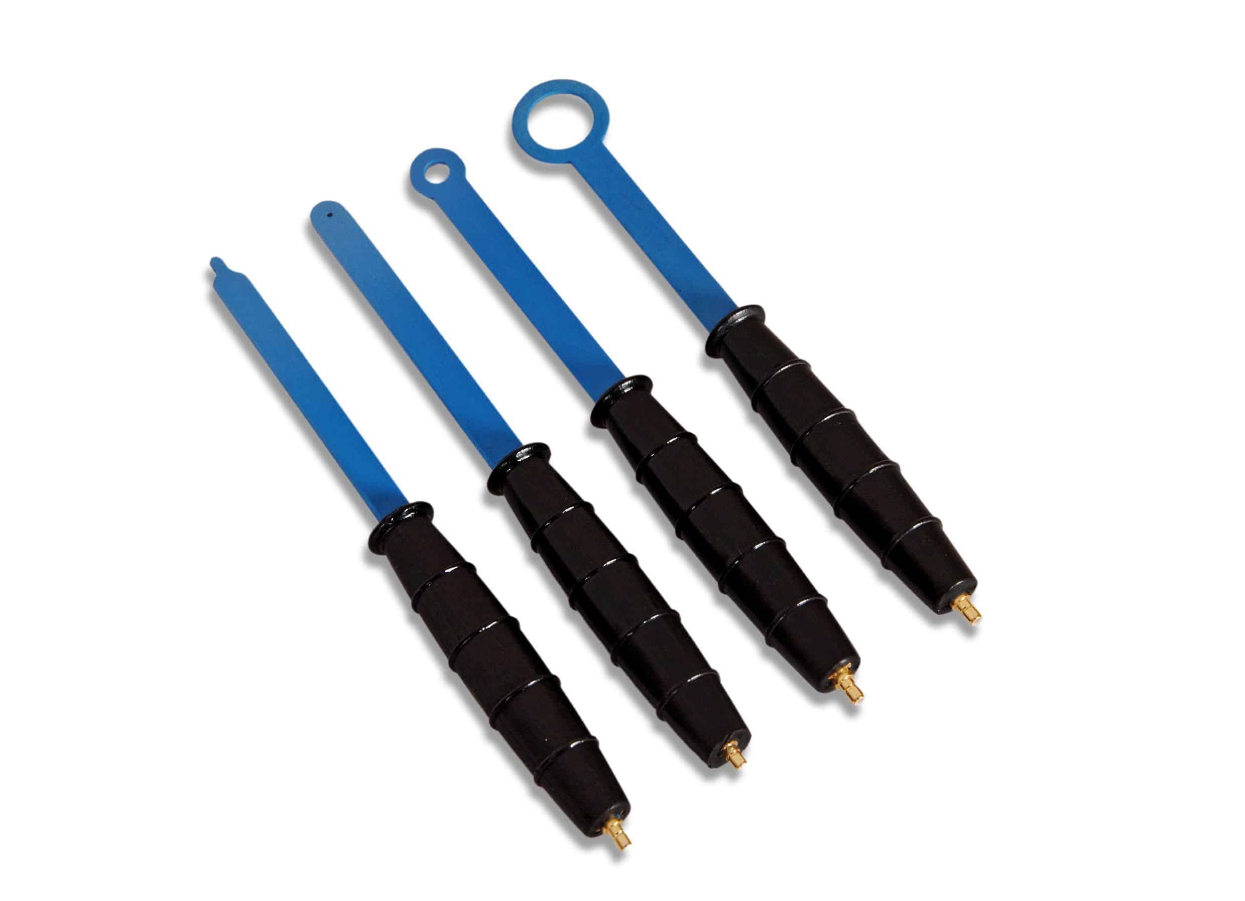
Tekbox Near Field Probes
Current Clamps/Monitor Probe ($10-$1000)
Current clamps (aka current monitors) can give you a very good idea of the emissions problems you'll see at a test lab due to common mode currents on external cabling. The extrapolation to a far field measurement is actually pretty good for common mode emissions up to around 200 MHz.
Some standards, such as CISPR 14 even call for the use of cable current clamps for use up to 1000 MHz.
However for pre-compliance measurements above 200 MHz, where wavelengths become small enough that features of a circuit board and enclosure can become effective radiators, the emissions from cabling aren't all we need to worry about.
A measurement of common mode current of around 5 uA on all external cables corresponds to a 'class B' pass/fail limit, whereas 15 uA corresponds to the lower 'class A' limit (very roughtly). See Henry Ott's guide for more information.
You can either buy new calibrated current clamps, or make your own.
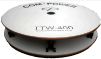
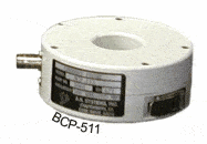
Antenna Mast and Turntable ($0 - $500)
Assuming you've bought a USB spectrum analyzer and antennas with gain data, you're doing well. To reduce the error budget more and get closer to the measurements of a full compliance lab, you'll want to move the antenna up and down and also rotate the EUT.
To rotate the EUT, you can just manually turn it in 90 degree (or less if you want) increments. The EUT should be sitting on a non-conductive table to avoid reflections. This will multiply your test time because you'll need to do a full sweep in each orientation.
If you want to level up and go with a fancy turntable, just go and buy a 'lazy susan bearing' for your non-conductive table to sit on. You can manually swivel the table during measurements, or even better, buy a brushless DC motor (to avoid noise issues) to turn the turntable remotely.
To mimic an antenna mast, you can use an adjustable tripod like this one, or the cheapest method would be to have a non-conductive support that you could set to a few different positions. Repeating the measurements at 2 or 3 height increments would at least help you to minimize this part of the error budget.
For most manufacturers who make more than 1 product per year, investing only $1k in pre-compliance test equipment doesn't make much financial sense. A failure can cost you as much in re-testing costs, not to mention the delay to market.
Leveling up to a modest $10k investment will get you much closer to a full compliance setup.
$10k - $15k Budget
Build a Low Cost OATS (Option 1)
 With a $10k budget, you're close to being able to afford a full compliance OATS. Fully compliant OATS are usually constructed according to ANSI C63.7 (Guide for Construction of Open-AreaTest Sites for Performing Radiated Emission Measurements) and/or CISPR 16-1-4.
Your ability to construct an OATS on this budget will depend on the availability of a large open site with utilities and a building/cabin. You could set this up in a large indoor loading bay or on a rooftop, but keep in mind that you want to minimize reflections off nearby walls, cables and metallic objects.
Here's what you need to buy with your $10k:
- Low cost spectrum analyzer ($1k - $5k)
At this price point, EMI receivers are not going to be within budget. I would look at a good, calibrated spectrum analyzer with frequency range 10 kHZ (so you can do conducted emission measurements too) up to 3 - 6 GHz. A few good options under $5k are the HP8560A, HP8563E and Agilent E4403B.
Buy them with a fresh calibration from a reputable cal lab (stickering without proper calibration is apparently rife).
- One or two calibrated antennas ($500-$3k)
A good broadband EMC (hybrid) antenna will get you from 30 MHz - 2 GHz which will cover many applications. They're a combination of a biconical and logarithmic antennas which may be called hybrid, bi-log, bicon-log etc.. depending on the manufacturer.
If you want more accuracy, split this job up into 2 antennas and buy both a bi-conical and a logarithmic antenna.
- Ground plane ($200 - $2500)
Your ground plane should be nice and flat and electrically contiguous (bonded at no more than every 1 inch). Chicken fence wire laid on top of flattened soil will be adequate in a pinch. A higher end solution is galvanized aluminum or steel with a minimum 16 gauge (otherwise welding gets very tricky and the plates bend in direct sunlight).
The size of this will depend on the antenna separation, but the smallest you would want to go is 8m x 10m. At smaller sizes, you'll have problems meeting the +/- 4 dB error budget.
- Manual or automated mast ($500- $5,000)
For maximizing the emissions, you'll need to vary the mast height between 1 meter at 4 meters. The mast needs to be non-conductive. If you're on a tight budget you could make one yourself or look out for used one on ebay.
- Manual or automated turntable ($10-$1k)
Again, for maximization, you need to be able to rotate the EUT 360 degrees. Ideally you'll have control of the turntable when you're standing next to the spectrum analyzer, so a motor controlled by remotely would be required. I bought a DC motor and variable speed controller from Ebay for under $500. If you're determined to cut costs, you can have someone else manually rotate the EUT.
- Software for creating plots and including transducer data ($0-$2,000)
To be able to include the transducer data (the antenna gain, cable attenuation and possibly an amplifier), labs normally use automation software. You could do it manually in a spreadsheet, but it would get laborious and would be more open to human error.
There are a couple of good options here: KE5FX - a free toolkit that let's you grab data across GPIB ports. With a bit of programming you could set this up to rip the spectrum analyzer data into a spreadsheet.
Probably the best option at the moment, if your spectrum analyzer is supported, is the EMCWare software from Amplifier Research. It's free and looks to be really comprehensive for emissions and immunity automated testing (I haven't personally used it).
Finally, some spectrum analyzers let you input the transducer data manually and the readings on the screen are compensated.
GTEM + Current Clamps ($7k-25k) (Option 2)
An alternative to a low cost OATS solution is to use a GTEM + current clamp.
GTEMs are not as accurate below 200 MHZ and great above 200 MHz (roughly).
Current clamps are not as useful above 200 MHZ and great below 200 MHz (roughly). See where I'm going with this?
 York EMC have investigated the GTEM thoroughly and produced a great app note on the subject.
Basically they have good correlation to an OATS down to about 200 MHz, then at the lower frequency range, the correlation drops right off.
Luckily for us, at the lower frequencies cable radiation starts to dominate. We can fill in the GTEM's deficiency by using a current clamp.
Now cable radiation isn't the only source of radiation at frequencies below 200 MHz, but it does account for a large proportion of failures below 200 MHz (I don't know what percentage, but at a guess >50%).
So with these two products, we can probably get to within +/- 10 dB of a full compliance test site.
GTEMs vary greatly in size and price. To meet the budget, you're going to need to watch ebay and test equipment auctions. I've seen used models as low as $5k and as high as $50k.
Update: We now offer benchtop TEM cells for under $1k. Check them out here.

$100k Budget
If you've got $100k to spend on an emissions pre-compliance test setup, you're in good shape. You're going to be able to meet the +/- 4 dB error budget and essentially do the same measurements as a full compliance lab.
You may want to think about registering your site with the FCC so that your own measurements are acceptable.
Full OATS ($20,000- $50,000)
The main differences from a 'cheap OATS' described above would be:
- Automated turntable and mast
You could invest in automated equipment so that you can accurately control the mast and turntable from beside the spectrum analyzer. Good automated equipment will have GPIB ports which feed the height and orientation data to a PC so that it is recorded in the measurement reports.
Some automated masts also have the capability to remotely change the antenna orientation from horizontal to vertical, which is a good feature if you're doing a lot of testing and every second counts.
On this budget you can just purchase automated equipment directly from the manufacturers. Modern automated equipment tends to be fiber optically controlled to avoid cable noise (and minimizes the antenna picking up noise from the automation equipment).
- EMI Receiver
You can also go high end with your measurement instrument. EMI receivers have a lower noise floor than their spectrum analyzer equivalents, they're faster and more importantly, they are usually CISPR 16 compliant (measurement bandwidths and detectors) which most spectrum analyzers are not.
- Weatherproof enclosure
If your OATS is outside (as opposed to a large loading bay), then it's open to the elements. Investing in a good non-conductive weatherproof enclosure will protect the EUTs and potentially the antennas and mast.
Some weather proof enclosures only cover the turntable, while preferably you cover both the turntable and the antenna. While some labs use wood for this, fiberglass is preferable. Wood can absorb moisture which can attenuate electric fields whereas fiberglass is pretty RF transparent.
Semi-Anechoic Chamber
Unless you find an amazing deal on a SAC, $100k will only just cover the cost of a used chamber.
You would want to make sure that the chamber is of dimensions that are capable of meeting NSA requirements (+/- 4 dB) and make sure that the absorbers/ferrites are still good.
The attenuation of these can degrade over time, so used chambers are susceptible to excessive reflections.
In terms of antenna separation, you should go for a minimum of 3 meters. 10 meter chambers are available and their price increases accordingly (>$1m).
The same advice applies as before to your choice of antennas, mast, turntable and automation.
LISN
Conducted Emissions Pre-Compliance
Conducted emissions pre-compliance is a lot simpler than radiated emissions pre-compliance because the test equipment requirements are so much smaller. There are not as many factors in play and everything is a lot less complicated. Basically a conducted emissions test setup only needs a low end spectrum analyzer and a line impedance stabilization network. We looked at the typical conducted emissions test setup in chapter 1 of this guide. Assuming you picked up a spectrum analyzer for radiated emissions compliance according to the specs above, then all you need to purchase is a LISN.
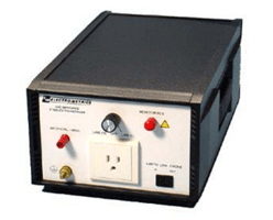
Line Impedance Stabilization Network
The type of LISN you need to buy really depends on the standard(s) that apply to your product. They vary in terms of frequency range, current rating and impedance (presented to the EUT). I haven't come across many low cost sources of LISN other than eBay. Keep an eye on there for used LISNs. Otherwise there are plenty of LISN manufacturers to choose from.
A full compliance LISN will typically cost less than $3k brand new, so it isn't hard to re-create a full compliance setup in your own office.
If you buy one of these and you have a calibrated low end spectrum analyzer, there would be no reason to ever fail conducted emissions at a 3rd party test lab again.
You could perceivably create your own LISN because the circuit isn't very complex, but you're working with line voltages and high currents so there is a significant safety risk.
Update: We now offer brand new LISNs for sale for under $1000 in our online store. View our LISNs here.
Conclusions
Hopefully this article outlines exactly what emissions pre-compliance equipment you should be thinking about purchasing for whatever level of budget you have available.
If you have any questions or you think there's something I've missed, please let me know in the comments section below.
Comments 11
In the bicon range (30Meg – 200Meg) if there is a horizontal seam or cable run on the ground plane then question is will the pickup be higher in the vertical polarization or horizontal polarization of the bicon, can you provide reasoning. Thanks.
Author
Hi Haris, sorry I don’t know the answer to this. A better person to ask may be an RF antenna designer.
measurements can be made on OATS in frequencies below 30 MHz?
Author
Yes, check out ANSI C63.4 section 5.3,
5.3 Radiated emission test facilities (9 kHz to 30 MHz)
For magnetic field strength measurements (see 8.2.1), a site similar to that shown in Figure 5 (Andy: An OATS), should be
used, except that a reference ground plane is not required. The site does not have to meet an NSA
requirement at these frequencies because NSA is based on electric fields. If a reference ground plane is
present, the measured level of emissions may be higher than if measurements were made without a ground
plane. The magnetic field strength measurements made at a site with no reference ground plane shall take
precedence. If permitted by the procuring or regulatory agency, measurements may also be made in a
shielded enclosure at frequencies below its resonant frequency, or in a TEM device (see Annex F).
Dear Good day, I wonder why is the site in ANSI, the extract of the standard 63.7 says that is used for the construction of test sites for freuencias 30 GHz to 18GHz / 40GHz.
Sorry I meant 30 MHz to 18 GHz / 40 GHz
Hello,
Do we require EMC chamber for measuring conducted emissions? For the CISPR-25 Standards.
thanks in advance
Author
For pre-compliance you don’t need a chamber. You should get reasonably close results just using a conductive table and potentially a conductive back wall. If you need to do full compliance measurements, you’ll need a chamber.
We are an agent for a chamber manufacturer now – let me know if you would like more information.
Best regards,
Andy.
But as I read the some EMC pre compliance testing documents I understand that the DUT must be placed on the wooden table which means a non conductive table and the LISN’s to be placed on conductive plane and one terminal of the LISN must be attached to ground plane. Is it correct in pre-compliance measurement? And we have to thnik to buy a chamber for the measuring of radiated emissions.
Thanks
In this article, you mentioned current clamps/monitor probe. When I went looking, I only found the one that you had included an image for other than units designed for specific oscilliscopes. Can you please let me know who sells these clamps? As well, where does the low end of the pricing for these clamps and probes come in? Is it for DIY devices. If so, do you know of any plans for such devices?
Thanks,
If I were to do a conducted pre-compliance testing at a EMC test lab or company instead of buying equipments for the test, what would they normally charge per day.
Thank you.