EMC TESTING: THE BEGINNER'S GUIDE
Chapter 3 - Continuous & Transient Immunity
You're going to need to consider immunity test requirements under lots of circumstances: If you're shipping to Europe or Australia (and many other specific regions), if you're using international product standards (published by IEC) or if your product is designed for a specific industry that mandates immunity testing (such as medical, military, aerospace and automotive to name a few).
In this chapter, we're going to cover what each of the main immunity test requirements are and how they may affect your product.
What is EMC Immunity Testing?
Immunity testing is just the application of some electromagnetic phenomena to your product. So you can think of it as the opposite of emissions testing. Instead of measuring what's coming from your product, immunity testing involves subjecting your product to EM phenomena.
Continuous vs. Transient EMC phenomena
Of the several EMC immunity tests, some are continuous (usually modulated) waves and others are very short bursts (transient) phenomena. The continuous tests are applied to your product over a period of time (minutes to hours). The transient phenomena may have come and gone in a matter of microseconds.
Here is a top level breakdown of the most common immunity phenomena:
What are the EMC Immunity Tests?
Despite the huge number of individual product and family standards covering many geographic areas and many industries, all of them come back to these base EMC immunity tests (or close variations of them) that I'm going to describe below.
Related Post: The In-House EMC Test Equipment Guide
Continuous
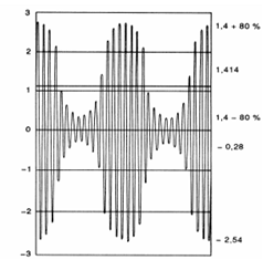
Continuous EMC phenomena are applied to your product over a period of seconds to minutes via a transducer.
Transient
Transient EMC phenomena are very short duration (ns to us) bursts of energy (voltage and current).
ESD Simulator
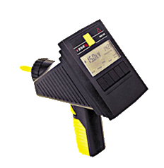
Discharge Tips
There are two types of discharge tips used for ESD testing. Here they are...

This is an 'air' discharge tip. During an 'air discharge' test, the tip is charged up to full voltage, then the tip is moved closer to the EUT. When the tips gets close to a conductive surface with a sufficiently large potential difference (usually ground), a spark will arc across to the device.

This is a 'contact' discharge tip. During an 'contact discharge' test, the uncharged tip makes contact with a point on the EUT. The test engineer then engages the trigger on the ESD simulator which charges the tip up to the test voltage and discharges the energy through the EUT (if a discharge path exists).
ESD - IEC/EN61000-4-2
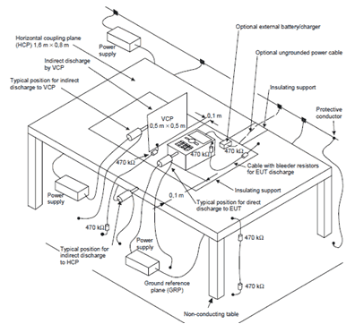 ESD testing is a very common form of EMC immunity testing. You know that little zap you get when you step out of your car and touch the metal?
That's ESD in action - your body (or the car chassis) accumulated a large voltage and when you touched the car, this voltage differential (of several kV) causes a spark to arc between you and the car.
ESD testing involves applying electrostatic discharges to any areas of your product that are normally accessible to a human touch.
Discharge Profile
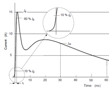
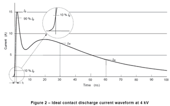 An electrostatic discharge to your product happens really quickly.
As you can see from the diagram, the bulk of the energy has dissipated within 100ns.
That means that any protection circuitry you select has to be able to react quickly to ESD events.
What test levels will be applied?
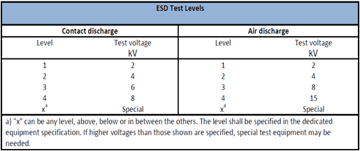
Here are some common test levels that are used when testing electronic devices. The test levels will be defined for your product in your product standard.
A very common test level is 4kV contact, 8kV air, but these values could be higher or lower depending on your standard.
A test lab will start at a low voltage (say 2kV), then if your product passes the lower level, they will increase the voltage and test again. Ideally your product will pass at the specified voltages, but often products exhibit some failure modes at lower levels.
What are some typical failure modes?
ESD tests can often be hard to pass. The short burst of high energy can cause lots of issues with your device. If you don't have adequate grounding and protection, here are some of the classic issues:
- Resetting
- IC port damage
- I/O communication failures
- LCD damage
- Memory corruption
- Digital logic errors
Radiated Immunity
Essential Equipment
- Semi-anechoic chamber (or GTEM)
- Signal generators (often 3 required to cover entire frequency range)
- RF broadband power amplifiers (also often 3 required)
- Automation software
- Antennas (Often need to use 2 or 3 types)
- Attenuators
Radiated Immunity (IEC/EN61000-4-3)
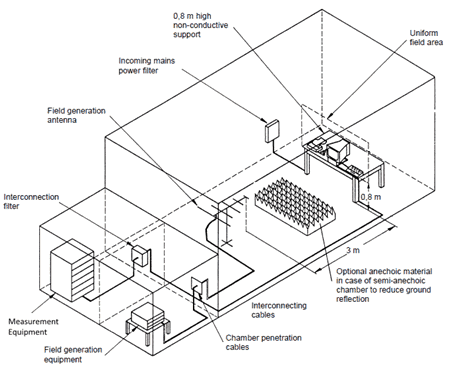 The theory behind the radiated immunity test is that your device will encounter many different types of electric field disturbances in normal usage.
Someone might use a cellphone next to it; someone might operate a motor next to it. There are lots of electric field sources that may interact with your device.
This test is intended to see how well your product performs when it's subjected to an electric field of a specified amplitude (measured in volts/meter) across a range of frequencies.
Radiated Immunity Field
During this test, your equipment is going to be subjected to a uniform electric field. The test lab has calibrated the field at several points around the test area that your product will sit within.
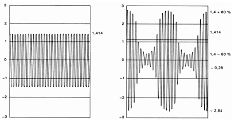 The field is generated in this way: A signal generator feeds a modulated sine wave to a broadband RF power amplifier. The output of the amplifier is connected to a transducer (an antenna), which turns the varying conducted voltage into a varying radiated electric field.
The field is usually modulated at 80% with a 1 kHz sine wave. For some standards, the modulation frequency and depth are different.
Typical Test Levels
- 1 V/m
- 3 V/m
- 10 V/m (industrial)
- >200 V/m (military + automotive)
Typical Frequency Ranges
- 80 MHz - 1 GHz
- 1.4 - 2.0 GHz
- 2 - 2.7 GHz
- Other standards may reach higher and lower.
What are some typical failure modes?
Radiated electric fields are most often picked up by a product's external cabling. That's because at the lower end of the radiated immunity frequency range, cables of length 1-3 metres can act as really effective receiving antennas.
At the higher frequencies, traces on your PCBs begin to become more effective at receiving energy from electric fields. The field can induce voltages on both analog and digital signals, so you can imagine that there is a host of issues that this can cause.
Here are a few of the common ones:
- Measurement errors (for EUTs with analog sensing)
- Wireless interference (for EUTs with transmitters)
- 1 kHz audio (The EUT often demodulates the modulation signal)
- Digital logic errors (if your eye diagram is very small and signal integrity is poor)
Electrical Fast Transient (EFT) - IEC/EN61000-4-4
The EFT immunity test is an attempt to simulate switching of inductive loads in the real world. Here are a few examples of inductive load switching that could perceivably affect your product:
- Toggling electric switch nearby
- Bundled cables can capacitively couple disturbances from switched loads other cables
- Motors and relays
- Fluorescent lamp ballasts
So what do the EFT disturbances look like?
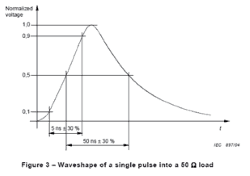 EFT is a transient EMC immunity test, so the disturbances happen very quickly.
To the right is an example of an EFT pulse. For this particular pulse, the voltage risetime is approx 5ns with a pulse width of approximately 50ns.
There are other profiles of EFT pulses for different standards but this is the most common for 61000-4-4 compliance.
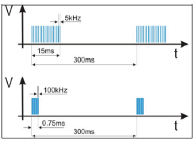 The test involves several 'bursts' of these pulses, with a delay inbetween bursts. The length of the bursts, the frequency of the pulses and the delay between bursts varies between standards. But here you can see a couple of the most common configurations.
Where will EFT be applied to your product?
There are a couple of injection points and methods for EFT. The first and most common is via an AC power cable. Even if you're using an external AC-DC power adapter, an EMC lab will most likely still inject EFT pulses onto the line and neutral wires.
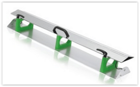
Also, EFT is normally applied capacitively to signal/control ports who's cables will be >3m in length. For capacitive coupling, the signals are simply fed through a capacitive coupling clamp, which couples the disturbance to the cables.
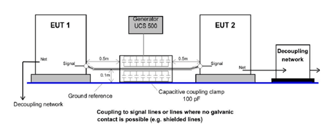
EFT
Essential Equipment
- EFT/burst generator
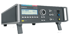
- Capacitive coupling clamp
- Automation software
Direct Coupling
For power ports, the EFT disturbances are injected directly onto the relevant signals with a carefully defined source impedance.
Capacitive Coupling
When EFT has to be applied to signal ports (e.g. USB, ethernet), the disturbance is usually applied capacitively using a clamp (see above) rather than direct injection.
What are some typical failure modes?
Energy from EFT testing can find it's way into many parts of your circuit. Entry points are via your power cable or other cables connected to your product, so without proper chassis grounding or common mode suppression, the disturbance can cause you some headaches.
Here are a few of the common issues:
- EUT resets
- Damage to ICs/hardware
- Failing auxiliary equipment
- Communications links drop out
- Temporary analog measurement errors
- Audible clicking (audio products)
Surge
Essential Equipment
- Surge simulator/generator
- CDN
- Automation software
Surge - IEC/EN61000-4-5
 The surge immunity test is designed to simulate low frequency power surges.
Here are a few examples of places where you would expect to see surge events:
- Power switching events
- Insulations faults on the power grid
- Nearby switching reactive loads (e.g. motors)
- Fuses blowing (flyback voltage)
- Nearby (indirect) lightning strikes
A typical product plugged into a residential AC power socket can expect to see 3 x 6kV power surges per year!
Surge Coupling Methods
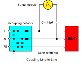 Surge is usually applied to AC (or DC) power input ports, but in some standards, it is also to be applied to signal ports.
The surge pulses are usually coupled directly to the signals via a carefully defined source impedance (e.g. 2Ω, 18uF in series).
The coupling network is usually contained inside an immunity test system along with a decoupling network which helps to protect the power supply or auxiliary equipment.
What are some typical failure modes?
Surge testing involves a lot of energy. The currents involved can easily exceed 100A for a short period of time. With this amount of energy, it's really easy to do damage to your product.
Here are a few of the common issues:
- Frying ICs
- Cabling breakdown
- Thermal issues
- Arcing is common
- Damage to motor windings
Recommendations
- Use power supply with surge protection of correct rating (legitimate CE Marked supplies will have protection, but check the rating)
- Design in your own protection using protection components such as TVS diodes or MOVs etc.
- The location and routing of protection circuitry is critical to its effectiveness.
Conducted Immunity - IEC/EN61000-4-6
Conducted immunity testing is used to simulate the normal voltage and current environment of external power and signal cables.
When cables are bundled together the can have both capacitive and inductive coupling. This test simulates adjacent cabling by injecting a common mode disturbance into your cabling using a transducer.
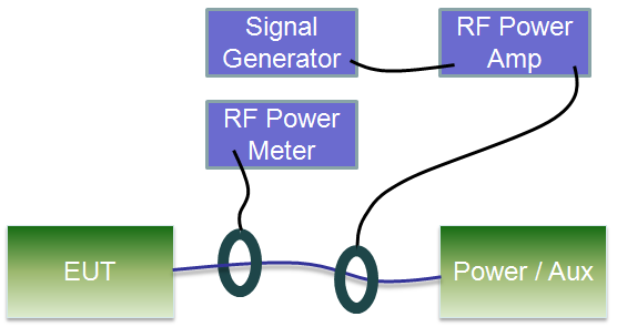
Conducted Immunity Transducers
CDN
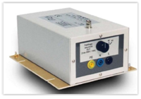
CDNs are the preferred transducer. They're not always used because you need a lot of them to cover different cable types and connectors.
BCI Probe
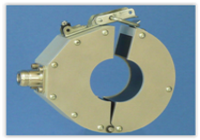
BCI probes are very convenient but it's hard to get repeatable results due to the unknown input impedance of the EUT and auxiliary equipment.
EM Clamp
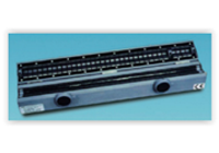
Also convenient, but again there are problems with repeatability of the tests. BCI probes are preferred over these.
Direct Voltage Injection

As a last resort, EN61000-4-6 allows the use of direct injection of the disturbance via a resistor.
What are some typical failure modes?
This test can be quite hard to pass because you usually have to meet criteria 'A' (see below for definitions).
Here are a few of the common issues:
- Audible rectification of the 1 kHz modulation frequency
- Measurement errors due to supply or signal ripple
- Resetting of ICs
Recommendations
- Apply RF common mode filtering to a cable interfaces (either low impedance capacitive filtering to chassis or high impedance common mode choke
- Consider cable screening with an effective range up to at least 200 MHz)
- Implement bandwidth limiting on analog input cabling
Magnetic Field Immunity
Essential Equipment
- Signal generator (if not powerline magnetic field testing)
- Variac
- Current Transformer
- H-field transducer (wire loop)
- Immunity test system (optional)
- Automation software (optional)
Magnetic Field - IEC/EN61000-4-8
 Some product standards call for magnetic field immunity testing.
The most common type of magnetic field immunity testing is what's called 'AC power line' which means that the magnetic field generating transducer will be driven with a 50/60 Hz signal to simulate the AC power supply.
This version of the test is to ensure that your product works properly in the presence of magnetic fields generated by nearby power cabling.
Some other magnetic field test variations involve sweeping a band of frequencies and also applying a modulation frequency.
How is the magnetic field generated?
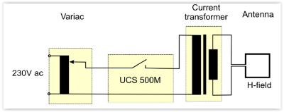 For power line magnetic field testing, the setup is pretty simple.
You can see from this diagram that a variac is connected to the mains AC voltage. The tap point of the variac define the voltage that's fed to a current transformer.
By varying the voltage, you can vary the current in the H-field antenna (the transducer) and therefore set the magnetic field strength (measured in Amps/m). The antenna just a loop or several loops of electrical wire. The varying current through these loops generates a magnetic field.
As you can see from the picture above, the EUT sits within the antenna so that it's subjected to a uniform magnetic field.
Which components are susceptible to magnetic fields?
There are a few types of components that can be particularly susceptible to magnetic fields. Often the test is exempted if your device doesn't contain and components that could perceivably be affected by a magnetic field. But, here are some to watch out for:
- Relays
- CRT monitors
- Hall elements
- Electrodynamic microphones
- Magnetic field sensors etc..
Voltage Dips, Drops & Interruptions - IEC/EN61000-4-11/-29
This EMC test is to simulate voltage dips and short brownouts on AC or DC power supplies.
It helps to ensure that your equipment functions properly (as expected and safely) with power supply fluctuations.
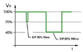 The duration of the voltage dip and the depth of the dip vary and are defined in your standard.
As you can see from this diagram, the dips happen for a period in the order of milliseconds.
For many pieces of equipment that use external AC/DC adaptors that operate down to lower voltages, this test rarely causes issues.
But issues often turn up for equipment that is connected directly to an AC or DC power supply.
Voltage Dips/Drops
Essential Equipment
- Immunity test system
- Auto-transformer
- Automation software
Recommendations
- Make sure your watchdog timer works properly
- Ensure the system reboots into an acceptable mode when the device resets
Voltage Dips Test Setup
For AC voltage dips and interruptions, the test setup will look something like this.
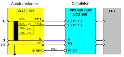 A tapped auto-transformer selects the dip level and an immunity test system controls the selection using an analog feed signal.
The immunity test system controls the length of the dip and switches between 100% and the dip signal to create the momentary drop in voltage.

Pass/Fail Criteria
To evaluate whether your product passes or fails each EMC immunity test, an EMC test lab needs to know what an acceptable degradation of performance actually is. They need to monitor your equipment during and after each test and watch for any changes to the behavior or operation.
The performance of your product usually falls into categories A,B,C and D, but this is dependent on the standard that applies to your product. The definitions below are taken from the European generic immunity standard for residential, commercial and light industrial environments (EN61000-6-1). Yours will probably look pretty similar.
 Criteria A, that's considered perfect. That means your product performs normally and within specifications that you specify, usually in the product manual, during and after the test.
So essentially nothing bad happened to your product during or after the test.
 Criteria B on the other hand, the product may have had a temporary loss of function or degradation of performance which ceases after the applied disturbance ceases.
So after the test finishes, the equipment under test recovers its normal performance without operator intervention. That just means that the operator didn't have to do anything to get it back into a mode that it was in before the test started.
 Criteria C is the same as B, but you're allowed operator intervention as well.
So maybe you have to power the device back on. Maybe the EMC phenomena reset the device and you need to power it back on manually.
 And criteria D is that there's a loss of function or degradation of performance which is not recoverable, owing to damage to hardware of software or loss of data.
So basically in some way the test has trashed your product. It might have fried some components or caused corruption of some data.
Conclusions
So those are the EMC immunity tests that your product may have to face. Now that you know what they are, you can begin to start thinking about how to prepare your designs for testing.
In the following chapters, we'll be digging into preparation and pre-compliance testing. You'll get a full view of how large companies set themselves up for success against EMC testing requirements!


Comments 21
Andy,
your article series is a great read. I hope you keep making these high interesting blogs.
Benno
Author
Thanks Benno
Hello Andy
Under “Radiated Immunity Field” section, what are the two pictures trying to show?
Left appear to be a sine wave whereas the one on the right appears to fluctuate follow a pattern.
Thanks.
Author
Hey Jacky. Those pictures are examples of modulated and unmodulated outputs from a signal generator. During the radiated immunity test, the signal is usually modulated with a 1 kHz sine wave, which you can see the effect of in the second picture.
Thank you bro.
Hello Andy,
Can you let me know why the signal is geneated this way? i.e. 80% of amplitude.
The field is usually modulated at 80% with a 1 kHz sine wave. For some standards, the modulation frequency and depth are different.
Dear Andy,
can you tell me what’s the difference between Voltage “dip” and “drop”?
in 61000-4-11 they use “periods”, does it have the meaning like “cycle” ?
Thank you.
Gang
what is the best DVM to use when measuring the output of the DUT while test Radiated Immunity at 100v/m 80% 1k modulation. All the digital meters I use are affected buy the Test signals.
Author
That’s a higher test level than most immunity tested meters will have passed. A few options:
1. Look for MIL STD or other rugged spec multimeter that meets those test levels
2. Shorten cables to minimum possible length
3. Insert fiber optic converter between voltage probes and meter
4. Make low pass filter with bandwidth below 1 kHz and insert between probes and meter
Andy.
Hello Andy
Can you refer to the time ynchronization methods between the EM interference source and the UUT in order to enable the recovering of the system state in the moment of specificatin deviation in the unit?
Gershon.
Dear Sir,
I just have a following doubt. Could you please reply to my question.
Testing on Differential (L-N) and Common mode (L-PE & N-PE) lines were mentioned in IEC 61000-4-5 (Surge test).
Testing for common mode is understandable in case of 3 wire AC units. Where as, I am unable to understand Common mode testing on DC 2 line units.
Is surge test applicable on DC 2 line powered units?
Please reply and send the response to [email protected].
Thanking you.
Yours faithfully,
Balakrishna.
Hi ,
1) Is it test pass/ fail criteria defined by the manufacturer will are mentioned in the test report ?
2) How to choose the test points for ESD test for contact discharge and for air gap discharge?
3) is the any of the result in the immunity results either A,B,C,D any of these are acceptable for CE certification?
D is definitely not acceptable for CE Certification, as your product is destroyed. Who’s going to buy a product that can be damaged/destroyed?
Hi ,
1) How to choose the passing criteria? From the user or from the lab according to standard?
2) Criteria A or “PASS” is defined by the user or lab?
Pingback: The basics: What is EMC?
Pingback: Conducted RF Immunity Testing - Overview, Methods, & Equipment-Home Automation Brother's Technology
Hi,
under Conducted Immunity – IEC/EN61000-4-6 the written text before and after the picture seems to be the same.
Pingback: How To Create A Magnetic Field On Mars | Dr Bakst Magnetics
I want this book can you share in pdf format
I am trying to isolate and diminish stray voltage spikes and sags within my house and work environment.
The main surge protector has a VPR of 1000 L-L and 500 L-G. However, I would like to have the sub panels
equipped with surge protectors that have a VPR of 330 or better, but at least 400. Any suggestions?
Your articles are great and highly informative.